Online exhaust automatic control device

An automatic control device and exhaust device technology, applied in textiles and papermaking, fabric elongation, lighting and heating equipment, etc., can solve the problems of fabric quality, increase energy consumption, and affect vehicle speed, and achieve precise control Exhaust air flow, improve service life and reduce high temperature damage

Active Publication Date: 2021-11-26
江苏日新印染机械有限公司
View PDF8 Cites 0 Cited by
  • Summary
  • Abstract
  • Description
  • Claims
  • Application Information

AI Technical Summary

Problems solved by technology

[0003] The existing technology has the following deficiencies: the existing ventilation is usually perceived and operated manually, and the workers judge when the ventilation is needed and how long the ventilation time is based on experience. This control method cannot be accurate
If the exhaust time is long, the temperature in the drying room is too low, and the drying room needs to be reheated to the preset temperature, which will increase energy consumption; if the exhaust time is short, the humidity in the drying room will increase, which will affect the speed of the vehicle. , which affects the quality of the fabric, and the existing exhaust device has low flow accuracy when discharging hot air, making it difficult to control the temperature in the drying room

Method used


Image

  • Online exhaust automatic control device
  • Online exhaust automatic control device
  • Online exhaust automatic control device

Examples


Embodiment Construction

[0036] The preferred embodiments of the present invention will be described below in conjunction with the accompanying drawings. It should be understood that the preferred embodiments described here are only used to illustrate and explain the present invention, and are not intended to limit the present invention.

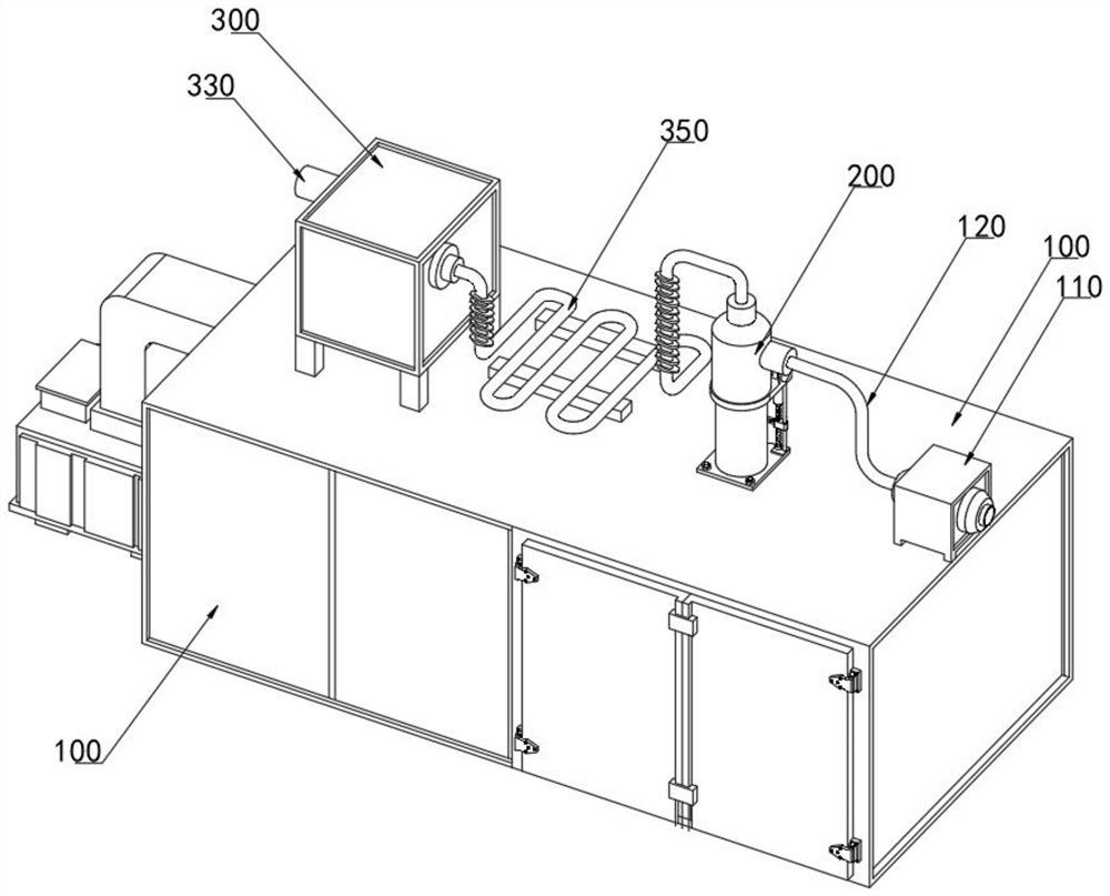
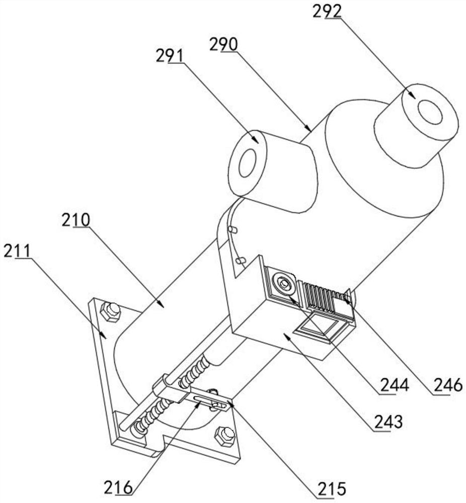
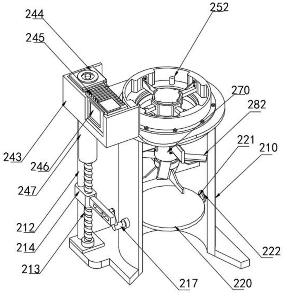
[0037] Refer to attached Figure 1-12, an online exhaust automatic control device provided by the present invention includes a base 100, a preset exhaust device 200 and a chassis 300, the base 100, the preset exhaust device 200 and the chassis 300 are used in conjunction with each other, and the preset exhaust The device 200 includes a bottom cover 210. Specifically, the top of the bottom cover 210 is provided with a support plate 240, the top of the support plate 240 is fixedly mounted with a support ring 250, the top of the bottom cover 210 is provided with a cover 290, and the bottom of the cover 290 is fixedly mounted on the support ring. 250 outer wall, the sup...


PUM


Abstract

The invention belongs to the technical field of textile printing and dyeing equipment, and particularly relates to an online exhaust automatic control device. The online exhaust automatic control device comprises a machine base, a preset exhaust device and a machine case, wherein the machine base, the preset exhaust device and the machine case are used in cooperation, the preset exhaust device comprises a bottom cover, a supporting disc is arranged at the top of the bottom cover, a supporting ring is fixedly installed at the top of the supporting disc, and a cover cap is arranged at the top of the bottom cover. A controller controls an air shield disc to be opened, a first negative pressure fan conducts air draft on the preset air exhaust device, the preset air exhaust device draws out hot air in a drying room, meanwhile, a temperature sensor detects the hot air, a temperature controller detects whether the temperature in the drying room reaches the standard or not, when the temperature in the drying room is too high, the controller controls the air shield disc to be opened, a second negative pressure fan and a plate cooler work at the same time, the second negative pressure fan pumps out hot air in the drying room through the preset exhaust device, and meanwhile, a humidity sensor detects the humidity of the hot air, so that an effect of precisely controlling the temperature of the drying room is achieved.

Description

technical field [0001] The invention relates to the technical field of textile printing and dyeing equipment, in particular to an online air exhaust automatic control device. Background technique [0002] During the textile printing and dyeing process, combustible gases such as natural gas are used to heat the drying room in the drying room of the stenter frame, which is dangerous. Therefore, it is necessary to regularly exhaust the drying room. [0003] The existing technology has the following deficiencies: the existing ventilation is usually perceived and operated manually, and the workers judge when the ventilation is needed and how long the ventilation time is based on experience. This control method cannot be accurate. If the exhaust time is long, the temperature in the drying room is too low, and the drying room needs to be reheated to the preset temperature, which will increase energy consumption; if the exhaust time is short, the humidity in the drying room will inc...

Claims


Application Information

Patent Timeline
IPC IPC(8): F26B25/00D06C3/00
CPCF26B25/005D06C3/00
Inventor 姜东日王东华
Owner 江苏日新印染机械有限公司
Why Eureka
Try Eureka