Measuring tool and method for measuring distance between linear rails of machine tool body
A bed and machine tool technology, applied in the field of measuring tools for measuring the line-rail spacing of the machine tool bed, can solve problems such as difficulty in ensuring the consistency of the line-rail spacing, dial indicator movement, and poor repeatability of measuring tools, so as to improve measurement accuracy and Repeated measurement accuracy, improved adaptability, good overall structural stability
- Summary
- Abstract
- Description
- Claims
- Application Information
AI Technical Summary
Problems solved by technology
Method used
Image
Examples
Embodiment 1
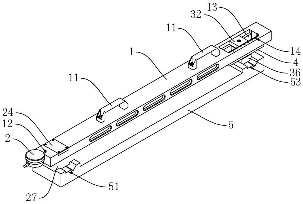
[0031] Embodiment 1: A measuring tool for measuring the line-rail distance of a machine bed, as shown in the figure, includes a frame 1, a first measuring unit and a second measuring unit, the frame 1 adopts a hollow design, and the upper side of the frame 1 is installed with Two handles 11, the first measuring unit is installed at one end of the frame 1, the second measuring unit is installed at the other end of the frame 1, the distance between the first measuring unit and the second measuring unit is the same as the line rail distance of the machine bed Adaptation, the line rail spacing of the machine bed is the distance between the left and right line rails on the machine bed.
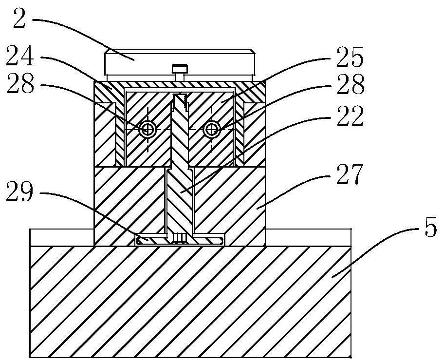
[0032] In Embodiment 1, the first measuring unit includes a dial gauge 2, a moving measuring head 22, a measuring pin 23, a sliding seat 24, a sliding block 25, a first spring 26 and a positioning block 27, and the sliding seat 24 is fixed on one end of the frame 1 , the slide block 25 can slide le...
Embodiment 2
[0035] Embodiment 2: Utilize the method for measuring the line-rail spacing of the machine tool bed implemented by the above-mentioned measuring tool, comprising the following steps:
[0036] (1) Place the measuring tool on the standard machine bed model 5, so that the first positioning part 29 at the bottom of the moving probe 22 fits the side contact surface 52 of a machine bed rail groove 51 on the standard machine bed model 5 , and make the second positioning part 37 at the bottom of the adjustable probe 31 fit the side surface 54 of another machine bed rail groove 53 on the standard machine bed model 5;
[0037] (2) Adjust the position of the measuring rod 21 of the dial indicator 2, so that the head of the measuring rod 21 bears against the measuring nail 23 on the slider 25. At this time, under the elastic action of the first spring 26, the slider 25 is at rest state, the measuring rod 21 of the dial indicator 2 produces a certain value due to the pressure, and then the...
PUM
 Abstract
Description
Claims
Application Information
 - R&D
- Intellectual Property
- Life Sciences
- Materials
- Tech Scout
- Unparalleled Data Quality
- Higher Quality Content
- 60% Fewer Hallucinations
Browse by: Latest US Patents, China's latest patents, Technical Efficacy Thesaurus, Application Domain, Technology Topic, Popular Technical Reports.
© 2025 PatSnap. All rights reserved.Legal|Privacy policy|Modern Slavery Act Transparency Statement|Sitemap|About US| Contact US: help@patsnap.com


