Method and device for wireless communication of sidelink

A wireless communication and wireless signal technology, applied in wireless communication, network traffic/resource management, electrical components, etc., can solve the problem that SL-CSI feedback is not timely, cannot reflect the state of the secondary link channel, and cannot meet the timeliness of SL-CSI. and other problems, to meet the requirements of timeliness and improve the transmission efficiency.

Pending Publication Date: 2021-11-26
SHANGHAI LANGBO COMM TECH CO LTD
View PDF0 Cites 0 Cited by
  • Summary
  • Abstract
  • Description
  • Claims
  • Application Information

AI Technical Summary

Problems solved by technology

However, the SR signal does not distinguish between different Tx UEs targeted by SL-CSI, nor does it distinguish between different SL-CSIs with different delay requirements, and one SR signal can only trigger one time-frequency resource allocation. When the CSI needs to be sent,

Method used


Image

  • Method and device for wireless communication of sidelink
  • Method and device for wireless communication of sidelink
  • Method and device for wireless communication of sidelink

Examples


Embodiment 1

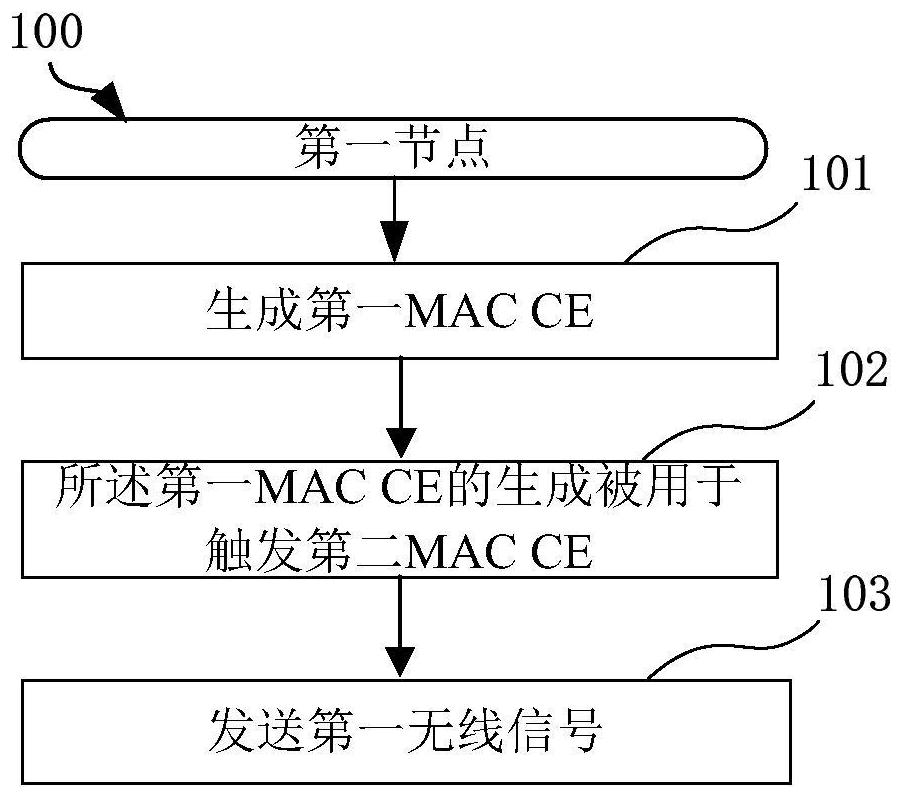
[0064] Embodiment 1 illustrates the flowchart of the first MAC CE, the second MAC CE and the first wireless signal according to an embodiment of the present application, as shown in the attached figure 1 shown.

[0065] In Embodiment 1, the first node 100 in this application generates the first MAC CE in step 101; the generation of the first MAC CE in step 102 is used to trigger the second MAC CE; and sends in step 103 A first wireless signal; wherein, the first wireless signal includes the second medium access control control element, and the second medium access control control element includes first information; the first information indicates a first cache size and a first time length, the first information indicates a first destination index; the first cache size indicates the size of the first data, and the first destination index indicates the destination of the first data Specifically, the first data includes the first medium access control control element; the first ...

Embodiment 2

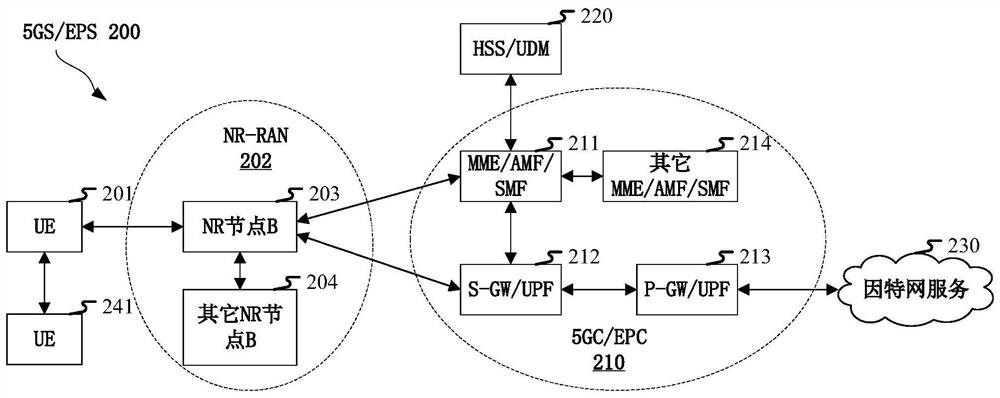
[0163] Embodiment 2 illustrates a schematic diagram of a network architecture according to the present application, as attached figure 2 shown. figure 2 A diagram illustrating network architecture 200 of NR5G, LTE (Long-Term Evolution, long-term evolution) and LTE-A (Long-Term Evolution Advanced, enhanced long-term evolution) systems. The NR 5G or LTE network architecture 200 may be referred to as 5GS (5G System) / EPS (Evolved Packet System, Evolved Packet System) 200 or some other suitable terminology. 5GS / EPS 200 may include one or more UE201, NG-RAN (Next Generation Radio Access Network) 202, 5GC (5G Core Network, 5G core network) / EPC (Evolved Packet Core, evolved packet core) 210, HSS ( Home Subscriber Server (Home Subscriber Server) / UDM (Unified Data Management, unified data management) 220 and Internet service 230. 5GS / EPS can be interconnected with other access networks, but these entities / interfaces are not shown for simplicity. As shown, 5GS / EPS provides packet-swi...

Embodiment 3

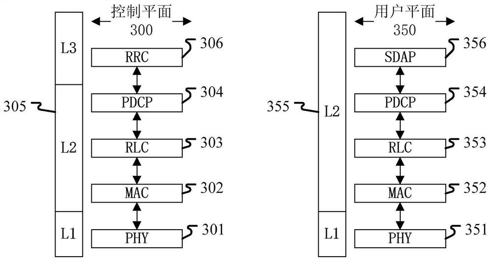
[0188] Embodiment 3 illustrates a schematic diagram of an embodiment of a wireless protocol architecture of a user plane and a control plane according to the present application, as shown in the attached image 3 shown. image 3 is a schematic diagram illustrating an embodiment of a radio protocol architecture for a user plane 350 and a control plane 300, image 3 Three layers are used to show the first node (RSU in UE or V2X, vehicle equipment or vehicle communication module) and the second node (gNB, RSU in UE or V2X, vehicle equipment or vehicle communication module), or two Radio protocol architecture of the control plane 300 between UEs: Layer 1, Layer 2 and Layer 3. Layer 1 (L1 layer) is the lowest layer and implements various PHY (Physical Layer) signal processing functions. The L1 layer will be referred to herein as PHY 301 . Layer 2 (L2 layer) 305 is above PHY 301, through which PHY 301 is responsible for the link between the first node and the second node and the ...


PUM


Abstract

The invention discloses a method and device for wireless communication of a sidelink. A first node generates a first media access control control element, the generation of the first media access control control element being used to trigger a second media access control control element, and sends a first wireless signal, the first wireless signal comprising the second media access control control element, and the second media access control control element comprising first information, wherein the first information indicates one of a first cache size and a first time length, the first cache size indicates the size of first data, the first data comprises the first media access control control element, the first time length indicates a time interval between a time domain resource occupied by the first wireless signal and a first reference time resource, and the first media access control control element is not scheduled after the first reference time resource. According to the invention, the method supports the timely transmission of a plurality of MAC CEs of the sidelink.

Description

technical field [0001] The present application relates to a method and a device in a wireless communication system, in particular to a method and a device for reporting buffer status in secondary link wireless communication. Background technique [0002] Buffer Status Report (Buffer Status Report, BSR) is a common method in the cellular network. The user sends a BSR to the base station to inform the base station of the amount of data waiting to be sent on the user side. The base station schedules transmission resources for the user according to the obtained data buffer information to realize data transmission. [0003] The application scenarios of future wireless communication systems are becoming more and more diversified, and different application scenarios put forward different performance requirements for the system. In order to meet the different performance requirements of various application scenarios, it was decided at the 3GPP (3rd Generation Partner Project, third...

Claims


Application Information

Patent Timeline
IPC IPC(8): H04W28/02H04W72/04H04W72/12
Inventor 张晓博
Owner SHANGHAI LANGBO COMM TECH CO LTD
Why Eureka
Try Eureka