
Vehicle speed control method and device based on speed compensation PID

A technology of speed compensation and vehicle speed, applied in the direction of control devices, etc., can solve the problem that the speed control accuracy cannot meet expectations, and achieve the effect of reducing speed deviation

Active Publication Date: 2021-11-30
WUHAN KOTEI INFORMATICS
View PDF7 Cites 0 Cited by
  • Summary
  • Abstract
  • Description
  • Claims
  • Application Information

AI Technical Summary

Problems solved by technology

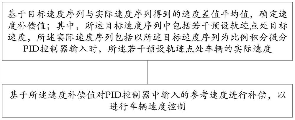
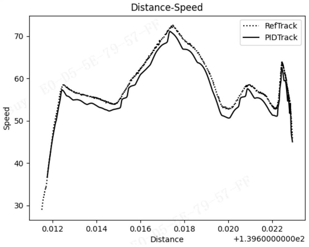
[0004]The above-mentioned published patents all focus on the stability of speed control. In the face of simulation scenarios that only require path tracking, that is, the reference trajectory only requires space matching and has nothing to do with time. , in response to such requirements, the PID control algorithm often performs well, but in the face of some scenarios that require trajectory tracking, that is, the reference path curve is related to both time and space, and the simulated vehicle is required to reach a predetermined time within a specified time. The reference path point means that the speed of the simulation vehicle reaching each reference path point needs to be consistent with the reference path point as much as possible. Due to the lag problem in the PID algorithm, the accuracy of the speed control cannot meet expectations

Method used


Image

  • Vehicle speed control method and device based on speed compensation PID
  • Vehicle speed control method and device based on speed compensation PID
  • Vehicle speed control method and device based on speed compensation PID

Examples


Embodiment Construction

[0039] In order to make the purpose, technical solutions and advantages of the present invention clearer, the technical solutions in the present invention will be clearly and completely described below in conjunction with the accompanying drawings in the present invention. Obviously, the described embodiments are part of the embodiments of the present invention , but not all examples. Based on the embodiments of the present invention, all other embodiments obtained by persons of ordinary skill in the art without creative efforts fall within the protection scope of the present invention.

[0040] In the face of simulation scenarios that only require path tracking, that is, the reference trajectory only requires spatial matching and has nothing to do with time. For such requirements, the PID control algorithm often performs well, but in the face of some scenarios that require trajectory tracking, that is, the reference path curve It is related to both time and space. It is requi...


PUM


Abstract

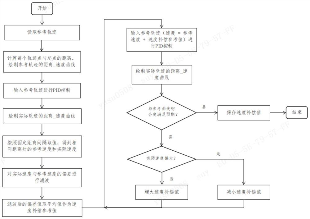
The invention provides a vehicle speed control method and device based on speed compensation PID. The method comprises the steps of building a PID control model which is relatively stable in control and has an error in an acceptable range through a speed compensation value, then increasing a speed compensation value for the speed of a reference track through changing the speed of the reference track inputted by the PID, and reducing the speed difference caused by PID lag. The speed compensation value is adjusted, so that the speed compensation value enabling the deviation between the actual speed and the reference speed to be minimum is found out, and the speed deviation caused by PID algorithm lag during track tracking can be reduced.

Description

technical field [0001] The invention relates to the technical field of automatic driving, in particular to a vehicle speed control method and device based on speed compensation PID. Background technique [0002] The PID control algorithm is widely used in the field of automatic driving. The algorithm inputs the current state of the vehicle model and the next expected trajectory, and outputs the steering wheel, accelerator and brakes used to control the model, so as to achieve the purpose of making the vehicle model drive according to the established trajectory. [0003] The Chinese invention patent with the notification number CN105404729A discloses "Improved PID speed control method based on driving situation map cluster in intelligent driving", which establishes a car model; then designs a speed control scheme; the speed of the smart car depends on the speed of the car model's own engine, The speed of the engine is controlled by the electronic throttle to the oil supply. W...

Claims


Application Information

Patent Timeline
IPC IPC(8): B60W30/18B60W40/105B60W50/00
CPCB60W50/00B60W30/18B60W40/105B60W2050/0052B60W2050/0011
Inventor 王军德余宿张进军
Owner WUHAN KOTEI INFORMATICS
Learn More