[0007]In a preferred embodiment, the
bearing surface on the side portion of the webs is designed as a planar surface extending as far as the bottom portion of the pocket. Such a
bearing surface or surface of the side portions of the webs can be provided or produced relatively simply, in particular can be manufactured, for example milled, in one operation. The bottom portion of the pocket in this case preferably consists of an angular transition of the side wall formed by the web of the pockets of one group into the opposite wall
lying in each case opposite the web. The bottom portion may, particularly at the transition, be provided with a preferably rounded longitudinal channel, said longitudinal channel forming a free surface for the circumferential zones of the legs of the chain links. It is particularly advantageous if the transitions or longitudinal channels of one group of pockets and the transitions or longitudinal channels of the other group of pockets lie offset with respect to a mid-plane of the sprocket. By virtue of this configuration, the sprocket width required overall and therefore also the overall weight of a corresponding sprocket can advantageously be reduced.
[0008]In another preferred embodiment, the
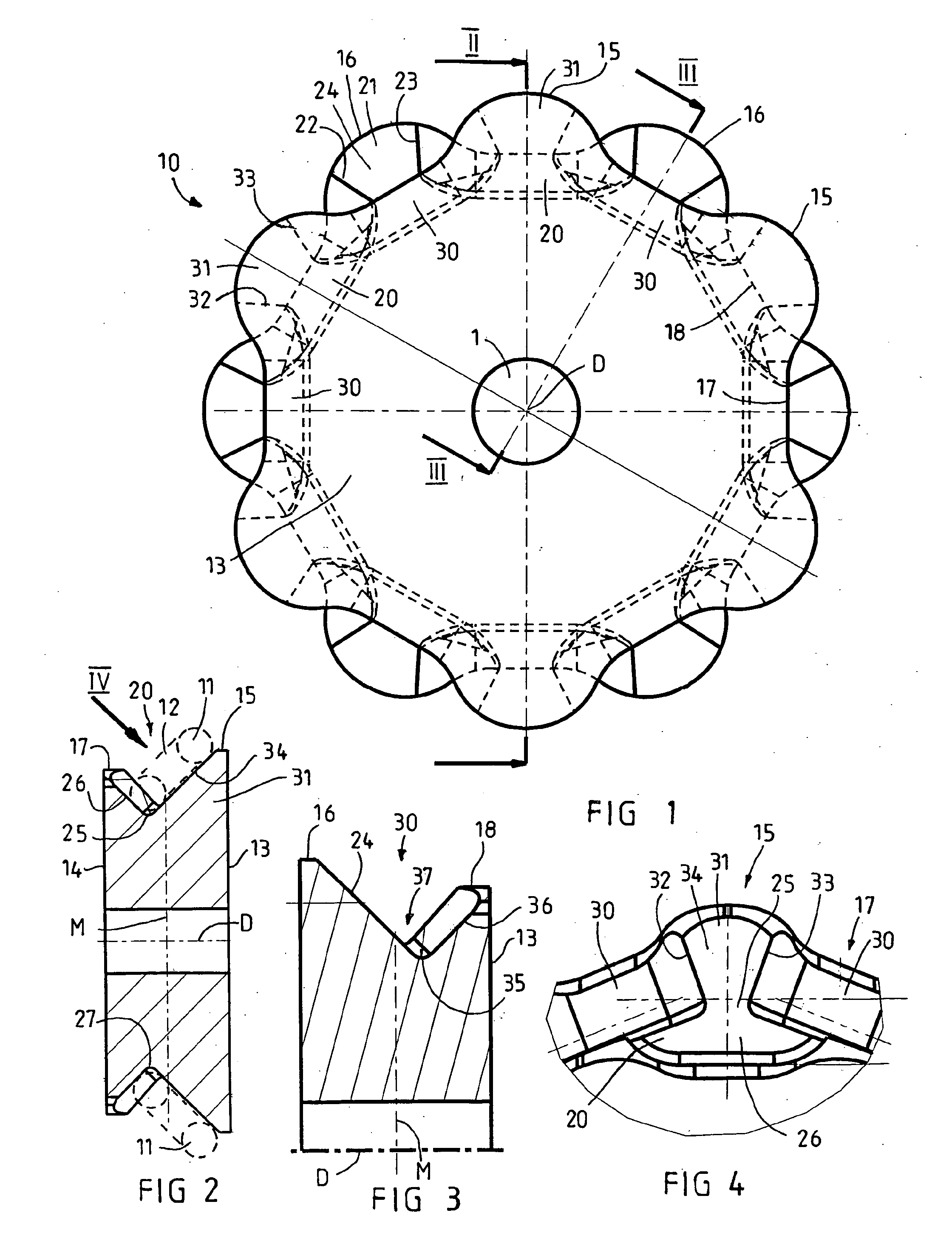
bearing surface on the side wall and the bearing surface on the opposite wall stand obliquely to the axis of rotation and at the same time at right angles to one another. A pocket with bearing surfaces, standing at right angles to one another, for the chain links can not only be produced particularly simply, but at the same time ensures a beneficial support of the chain links received in the pockets. In a most favorable instance, the respective chain links standing obliquely then run into the sprocket and out of the sprocket at an angle of 45°, so that successive chain links are also supported in their optimal 45° orientation on the bearing surfaces in the pockets
lying laterally and offset with respect to one another in the circumferential direction and at the same time are acted upon by the circumferential forces in the circumferential direction by means of the flank portions of the webs. In this case, it proves to be particularly advantageous that each
chain link rotating in the pockets of the sprocket forms a carrying
chain link which absorbs the circumferential forces which are to be introduced from the drive of the sprocket into the link chain. This gives rise, particularly also in comparison with the conventional configuration of chain links with horizontal carrying chain links and with vertical non-carrying chain links, to the particular
advantage that a substantially more beneficial distribution of forces to the individual rotating chain links occurs, the polygonal effect is minimized and substantially lower speed differences arise during rotation on account of the polygonal effect than was the case in the conventional sprockets or chain starwheels known in the prior art.
[0009]The geometry, simplified according to one aspect of the invention, of the pocket cross sections with bearing surfaces, running obliquely with respect to one another, on the side wall and on the opposite wall makes it possible that the sprocket can preferably be produced from or consist of a one-part blank or cast blank with preferably preformed pockets, if appropriate only the final form of the pockets being generated by means of milling methods and / or
grinding methods, and the surfaces occurring then acquiring wear protection, if appropriate, by means of hardening, annealing or the like. The simple pocket geometry, particularly with pocket bearing surfaces standing at right angles to one another and inclined at an angle of 45°, makes it possible that the sprocket can then be finish-machined in a fixture by means of relatively simple
machining tools and the pockets can acquire their desired geometry, including suitable roundings on the flank portions of the webs, in order to ensure a favorable run of the chain links into the sprocket and, during rotation, to achieve lower loads on the chain links
lying in the pockets. As a result, at the same time, vibrations which are introduced from the sprocket into the link chain and may lead to additional loads on the link chains or drive units, particularly when the link chains are rotating, also decrease.
[0011]Particularly for the use of the sprockets according to the invention in mining, such as, for example, mineral extraction (salt,
potash or the like) or
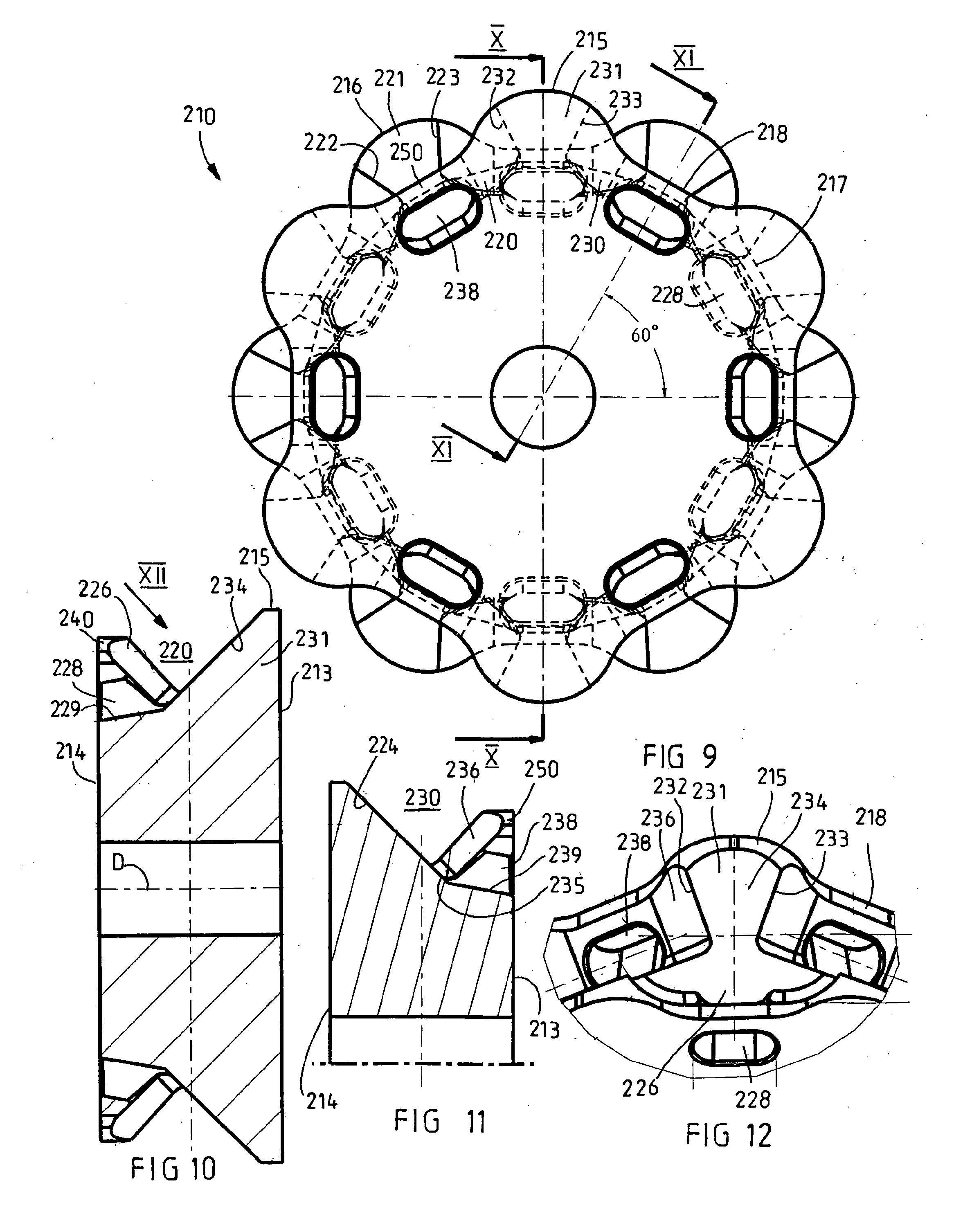
coal extraction, it is particularly advantageous if each opposite wall is provided with at least one displacement orifice for fine
coal, salts, rock or mineral accumulations or the like. According to an advantageous embodiment, the displacement orifices or expelling orifices consist of a passage in the opposite wall if, for example, the sprocket has on both side flanks a
peripheral closed margin or collar. It is particularly advantageous, however, if the webs are formed on tooth-shaped elevations on the two side flanks of the sprocket, and, between the elevations, sinks are provided which at least partially form the displacement orifices for fine
coal, dust, salts or the like. The combination of elevations and sinks with passages in the opposite wall may also afford particular advantages. Instead of passages in the opposite wall, the sinks could also be formed between the tooth-shaped elevations in such a way that they extend, at least in the middle of the pockets, as far as the pocket bottom, so that the individual pockets are consequently designed as “deep-drawn” pockets and are open toward the side flank in the region of the opposite wall. The cross section of these sinks forming the displacement orifices may, in turn, have approximately V-shaped profile, in order by means of the deep sinks to achieve large displacement orifices between tooth-shaped elevations which at the same time are of
robust design. In order to improve the displacement or
discharge of accumulations of fine coal or the like, which, in particular, are also inclined to briquetting and may thereby considerably impair the run-in behavior of the chain links into the pockets of the sprocket, the side flanks may be provided with
discharge slopes in the region of the passages or of the sinks extending to a great depth. The passages in the side flanks below the sinks may preferably consist of long holes. Both the configuration with sinks extending to a great depth and the configuration with long holes in the region of the opposite wall have the
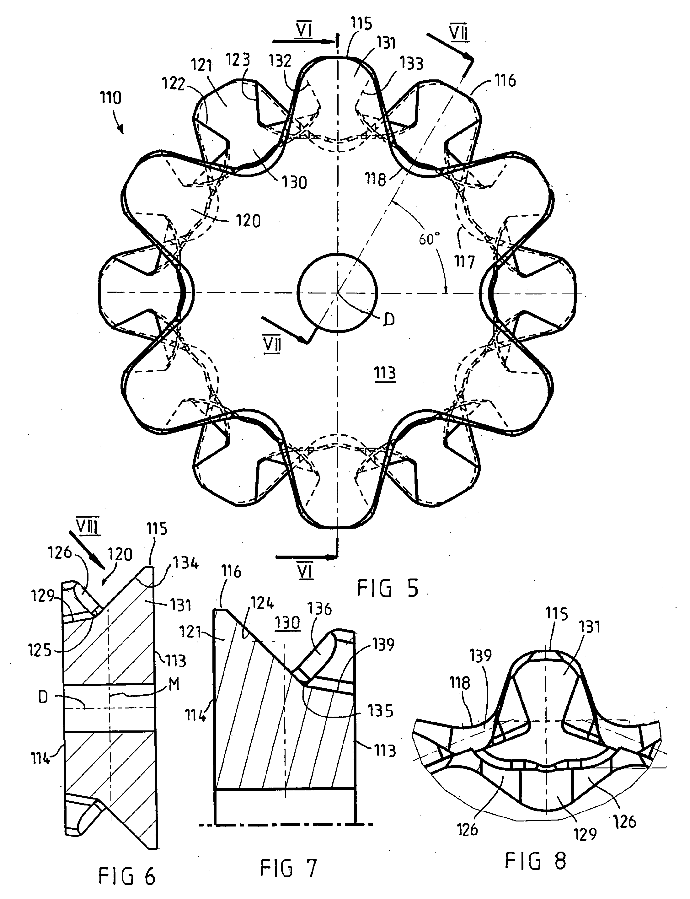
advantage that, when the chain link runs into the pocket, smaller rock fragments or briquetting could be pushed downward when a chain link runs into the pockets and could then be pressed away outward through the displacement orifices. According to an advantageous embodiment, each side flank may be provided in each case with 4 to 8 elevations and sinks, in particular with six elevations and six sinks, which are in each case spaced apart at 60° from one another, so that the sprocket overall has twelve pockets, of which in each case six pockets form a pocket row or pocket group.
[0012]The preferred field of use of a sprocket according to the invention with pockets which have lateral bearing surfaces, standing obliquely with respect to one another, with the chain links running in at an angle of 45° is as a driving or deflecting sprocket for the planing chain of a mining plane for mineral or coal extraction or for the scraper chain of a scraper
chain conveyor for mineral extraction, coal extraction or mining. When the sprockets with pockets are used for chain links running obliquely, because all the chain links, as carrying chain links, transmit the circumferential forces introduced by means of the drive to the link chain, the loads on the chain links when they rotate in the pockets of the sprocket are reduced. This gives rise to markedly more beneficial distributions of forces to the carrying chain links, and the wear of the chain links when they rotate about the sprocket falls, while at the same time vibrations introduced into the rotating chain are reduced. In scraper chain conveyors, there is the further
advantage that the chain can be drawn in this 45° oblique position through the trough sections of the scraper
chain conveyor or can run through the trough sections, the oblique position of the chain links of the chain making it possible to have a lower overall height both of the conveying strand and of the return strand for the scraper chain. Since, in a link chain with chain links running obliquely, both chain links are supported on the bottom of the conveying strand and return strand, the wear on the conveyor bottom or on the bottom of the lower strand decreases at the same time. The
system technology involved in the use of sprockets with pockets for chain links entering the sprocket obliquely can therefore, overall, improve the useful life of scraper chain conveyors and of underground mining installations.

