Steering gear gap adjusting mechanism and method and vehicle

A technology of clearance adjustment and steering gear, applied in the field of auto parts, can solve the problems of inability to respond quickly and the response can only be linear, and achieve the effect of improving NVH performance, stable process and simple structure

Active Publication Date: 2021-11-30
ZHEJIANG WANDA AUTOMOBILE DIRECTION MACHINE CO LTD
View PDF4 Cites 0 Cited by
  • Summary
  • Abstract
  • Description
  • Claims
  • Application Information

AI Technical Summary

Problems solved by technology

Existing products generally use springs to eliminate the gap, but the working characteristics of the spring determine that its response can only be linear, and cannot respond quickly to eliminate the gap in time

Method used


Image

  • Steering gear gap adjusting mechanism and method and vehicle
  • Steering gear gap adjusting mechanism and method and vehicle
  • Steering gear gap adjusting mechanism and method and vehicle

Examples


Embodiment 1

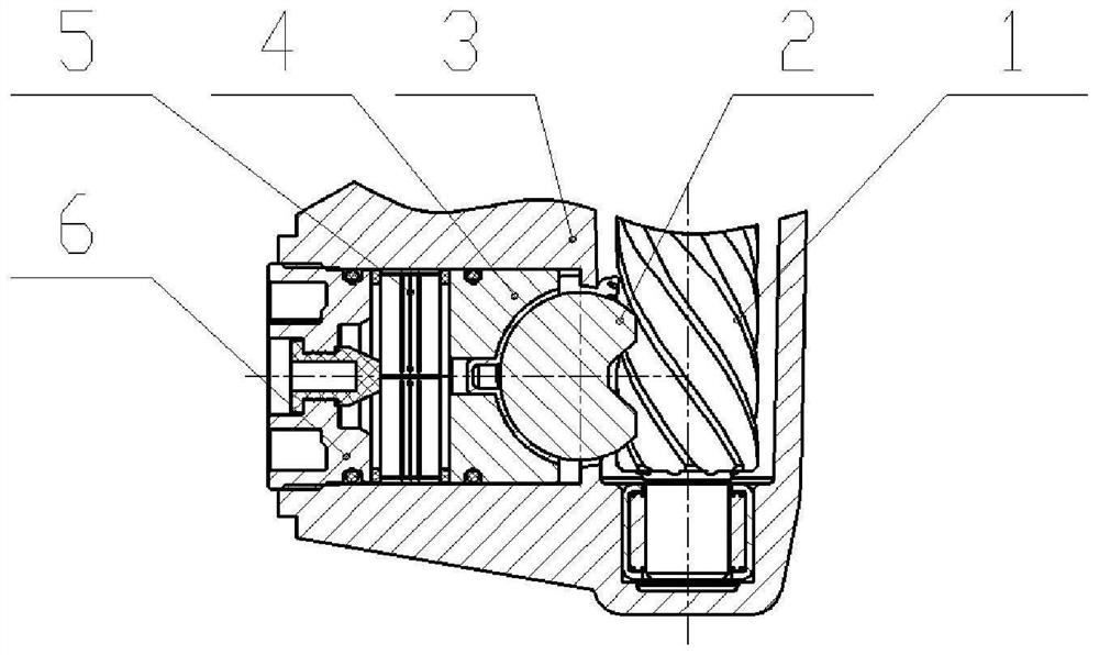
[0039] see Figure 1 to Figure 7 As shown, a steering clearance adjustment mechanism includes a housing 3 , a gear 1 , a rack 2 , a pressing block 4 , a bushing 5 and an adjusting screw plug 6 . The gear 1 and the rack 2 mesh with each other in the housing 3 , and the housing is provided with an adjustment hole, and the adjustment hole is connected with a gap adjustment assembly for adjusting the gap between the gear 1 and the rack 2 . Specifically, the gap adjustment assembly includes a pressure block 4 that is movably connected to one end of the adjustment hole and pressed to the rack, an adjustment screw plug 6 that is threadedly connected to the other end of the adjustment hole, and a pressure block 4 and the adjustment screw plug 6. The bushing 5 acts on the pressing block 4 and is used to limit the radial movement of the rack 2 along the gear 1 .

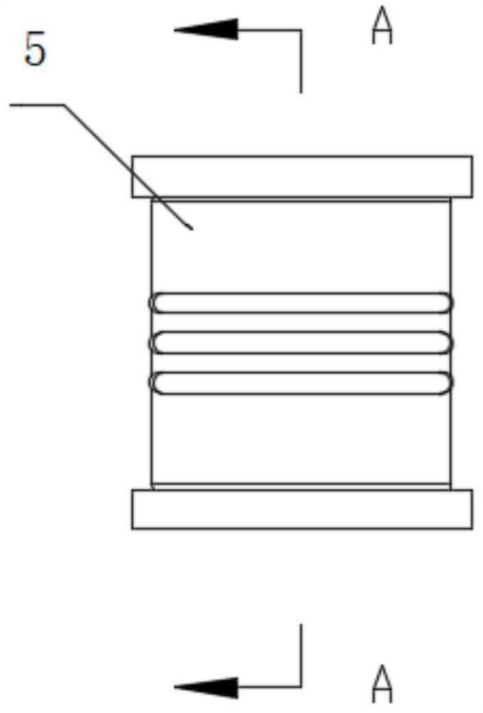
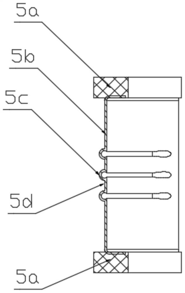
[0040] Among them, such as Figure 2 to Figure 4 As shown, the bushing 5 includes a steel ring 5b and a rubber block 5a, a...

Embodiment 2

[0048] refer to figure 1 with Figure 8 As shown, the gap adjustment method corresponding to the above-mentioned steering gear gap adjustment mechanism includes the following steps:

[0049] (1) Adjust the initial clearance of the steering gear by adjusting the initial position of the adjusting screw plug, and pre-compress the bushing. At this time, the rubber block of the bushing undergoes compression deformation, and the steel ring undergoes certain buckling deformation, so that the working force of the bushing - the displacement curve is in the linear segment;

[0050] (2) There is a gap between the gear and the rack due to work wear or the rack moves back and forth in the radial direction when the vehicle is driving on a bumpy road;

[0051] (3) The rack moves to the left in the radial direction (that is, away from the gear direction), pushing the pressing block to move to the left, compressing and deforming the bushing, generating axial force, restraining the pressing b...

Embodiment 3

[0056] A vehicle is equipped with a steering gear, and the steering gear is provided with the steering gear clearance adjustment mechanism of the first embodiment.


PUM


Abstract

The invention discloses a steering gear gap adjusting mechanism and method and a vehicle. The steering gear gap adjusting mechanism comprises a shell, a gear and a rack, wherein the gear and the rack are arranged on the shell; the gear is meshed with the rack, the shell is provided with an adjusting hole, and the adjusting hole is connected with a gap adjusting assembly used for adjusting the gap between the gear and the rack; the gap adjusting assembly comprises a pressing block which is movably connected to one end of the adjusting hole and is pressed on the rack, an adjusting screw plug which is in threaded connection to the other end of the adjusting hole, and a lining which is positioned between the pressing block and the adjusting screw plug; in the initial state, the initial gap of the steering gear is adjusted by adjusting the initial position of the adjusting screw plug, and the lining is pre-compressed to be bent and deformed; in the working state, the gap between the gear and the rack is eliminated through deformation of the lining. The gap change of the steering gear under the bumpy road condition can be quickly responded, the process is stable, and abnormal sound is reduced.

Description

technical field [0001] The invention relates to the technical field of auto parts, in particular to an auto steering system. Background technique [0002] With the intensification of competition in my country's auto market and the development of new energy vehicles, consumers have increasingly stringent requirements for car performance, and car comfort such as vibration and noise has gradually become one of the main considerations for consumers when purchasing cars. one. Therefore, the NVH (Noise, Vibration and Harshness) performance of automobiles will receive more and more attention. In particular, the excitation of the road to the steering gear can be directly perceived by the driver, which seriously affects the driving comfort and handling stability of the car. [0003] There is a certain meshing gap between the steering gear rack and pinion. After a long time of work, the steering gear rack and pinion will wear out, which will cause the meshing gap between the two to e...

Claims


Application Information

Patent Timeline
Patent Type & Authority Applications(China)
IPC IPC(8): B62D3/12F16H57/12
CPCB62D3/12F16H57/12F16H2057/126
Inventor 汪耀高艳军孙祖明
Owner ZHEJIANG WANDA AUTOMOBILE DIRECTION MACHINE CO LTD
Why Eureka
Try Eureka