Storage device for special aluminum oxide

A storage device and alumina technology, which is applied in packaging, transportation and packaging, transporting passenger cars, etc., can solve problems such as deterioration of alumina powder, uneven heating of alumina powder, incomplete drying of alumina powder, etc., and achieve reduction Waste of resources, avoid incomplete drying, and improve drying efficiency

Active Publication Date: 2021-11-30
苏州盛曼特新材料有限公司
View PDF10 Cites 1 Cited by
  • Summary
  • Abstract
  • Description
  • Claims
  • Application Information

AI Technical Summary

Problems solved by technology

[0005] In order to overcome the disadvantage that the alumina powder located in the middle is relatively far away from the inner wall of the storage bin, so that the alumina powder is heated unevenly, and then the drying of the alumina powder is not complete, resulting in the deterioration of the alumina powder during storage. The present invention Provide a storage device for special alumina

Method used


Image

  • Storage device for special aluminum oxide
  • Storage device for special aluminum oxide
  • Storage device for special aluminum oxide

Examples


Embodiment 1

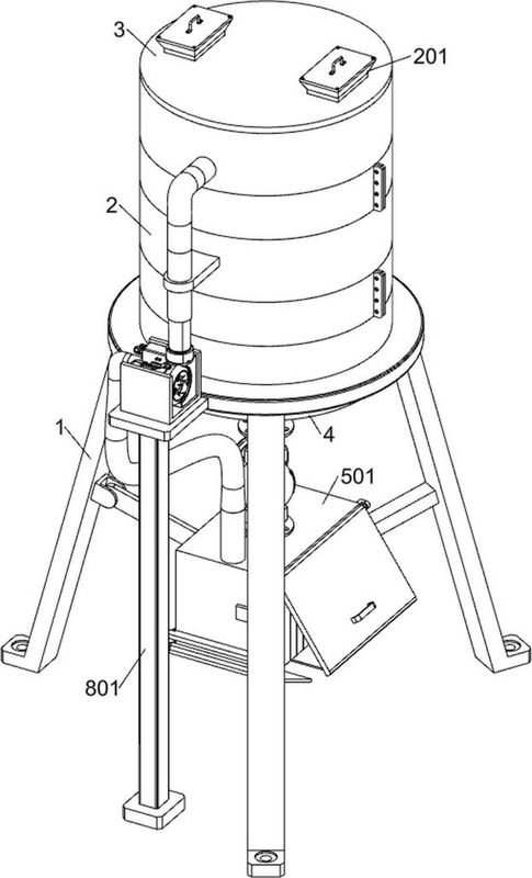
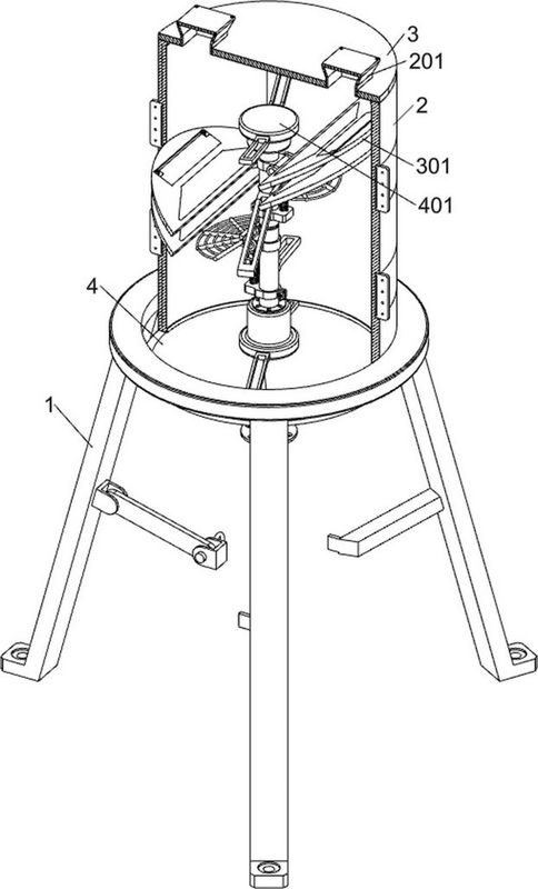
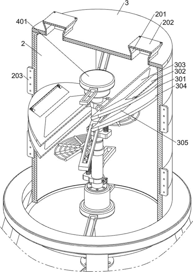
[0032] A storage device for specialty alumina, such as Figure 1-4 As shown, it includes a first frame 1, a first tank body 2, a first top cover 3, a first bottom cover 4, a first line column 401, an outer ring drying assembly, a split flow drying assembly and a middle drying assembly The upper part of the first frame 1 is fixedly connected with the first tank body 2; the upper part of the first tank body 2 is fixedly plugged with the first top cover 3; the lower part of the first tank body 2 is welded with the first bottom cover 4; The middle part of the body 2 is fixedly connected with the first line column 401 through the connecting frame; the outer ring drying assembly is installed on the outside of the first tank body 2; the outer ring drying assembly is connected with the first top cover 3; the inner side of the first tank body 2 is upper right A split flow drying assembly is installed at the top; another split flow drying assembly is installed at the inner left middle o...

Embodiment 2

[0039] On the basis of Example 1, such as figure 1 and Figure 5-7 As shown, a sealing assembly is also included. A sealing assembly is installed inside the first frame 1. The sealing assembly includes a first limit frame 501, a first support frame 502, a first motor 503, a first transmission rod 504, a first Cover plate 505, first spur gear 506, second transmission rod 507, second spur gear 508, first transmission wheel 509, second support frame 5010, third transmission rod 5011, second cover plate 5012, second transmission wheel 5013, the second motor 5014, the fourth transmission rod 5015, the third cover plate 5016, the first rubber curtain 5017, the first valve 5018 and the first pipe 5019; the inside of the first frame 1 is fixed with the first limit frame 501 ; The lower part of the front side of the first limiting frame 501 is fixedly connected with the first support frame 502; the first motor 503 is installed on the left part of the first support frame 502; the first...

Embodiment 3

[0042] On the basis of Example 2, such as figure 1 and Figure 8 As shown, a collection assembly is also included, the collection assembly is installed in front of the first frame 1, and the collection assembly includes a third support frame 801, a first pump machine 802, a second pipeline 803, a third connecting block 804 and a third pipeline 805; a third support frame 801 is installed in front of the first frame 1; a first pump 802 is installed on the top of the third support frame 801; a second pump 802 is connected between the input end of the first pump 802 and the first limit frame 501 The pipeline 803; the third pipeline 805 communicates between the output end of the first pump 802 and the first tank body 2; the third connection block 804 is fixedly connected to the middle of the first tank body 2; the third pipeline 805 penetrates and is fixed on the third connection on block 804.

[0043] When the alumina powder was impacted and dispersed in the first limiting frame...


PUM


Abstract

The invention relates to the field of aluminum oxide storage, in particular to a storage device for special aluminum oxide. The technical problems to be solved are that aluminum oxide powder located in the middle is relatively far away from the inner wall of a storage bin, so that the aluminum oxide powder is heated unevenly, then the aluminum oxide powder is dried incompletely, and the aluminum oxide powder goes bad in the storage process. According to the technical implementation scheme, the storage device for the special aluminum oxide comprises a first rack, a first tank body, a first top cover and the like; the first tank body is arranged at the upper part of the first rack; and the first top cover is fixedly connected to the upper part of the first tank body. When the storage device is used, the aluminum oxide powder is injected, and meanwhile, the aluminum oxide powder is automatically subjected to split-flow preheating, so that the drying efficiency is greatly improved, the aluminum oxide powder is automatically dried from the inner side and the outer side at the same time, and the phenomenon that the aluminum oxide powder is not dried completely is avoided.

Description

technical field [0001] The invention relates to the field of alumina storage, in particular to a storage device for special alumina. Background technique [0002] Industrial alumina is prepared from bauxite and diaspore. For alumina with high purity requirements, it is generally prepared by chemical methods. [0003] In the prior art, when the alumina powder is stored, the alumina is heated to volatilize the moisture in the alumina powder to avoid deterioration. When the existing equipment is used to dry the alumina powder, the storage The inner wall of the silo conducts heat to the alumina powder, and the alumina powder is piled up in the storage silo in a cylindrical shape, so that the alumina powder in the middle is relatively far from the inner wall of the storage silo, so that the alumina powder is heated unevenly, which in turn makes the Incomplete drying of alumina powder leads to deterioration of alumina powder during storage. [0004] Therefore, there is a special...

Claims


Application Information

Patent Timeline
Patent Type & Authority Applications(China)
IPC IPC(8): B65D88/74B65D90/00
CPCB65D88/747B65D88/744B65D90/00
Inventor 张举张兰银
Owner 苏州盛曼特新材料有限公司
Why Eureka
Try Eureka