
Dewatering structure for preventing underground structure from floating upwards and construction method thereof

An underground structure and groundwater level technology, applied in infrastructure engineering, protection devices, buildings, etc., can solve problems such as leakage and dewatering wells, complicated construction procedures, and stoppage of operation, so as to avoid anti-floating damage and directly resist floating. Effective and rust prevention effect

Pending Publication Date: 2021-11-30
新城控股集团实业发展有限公司
View PDF9 Cites 0 Cited by
  • Summary
  • Abstract
  • Description
  • Claims
  • Application Information

AI Technical Summary

Problems solved by technology

[0004] The purpose of the present invention is to provide a dewatering structure that prevents the underground structure from floating up, and solve the problems that the traditional bottom plate reserved dewatering tube wells have complex construction procedures, are prone to leakage in the later stage, and the dewatering wells are damaged or stopped operating during the construction of the main structure of the basement. question

Method used


Image

  • Dewatering structure for preventing underground structure from floating upwards and construction method thereof
  • Dewatering structure for preventing underground structure from floating upwards and construction method thereof
  • Dewatering structure for preventing underground structure from floating upwards and construction method thereof

Examples


Embodiment Construction

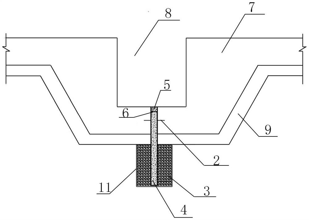
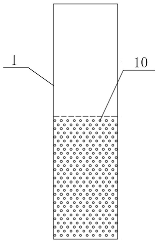
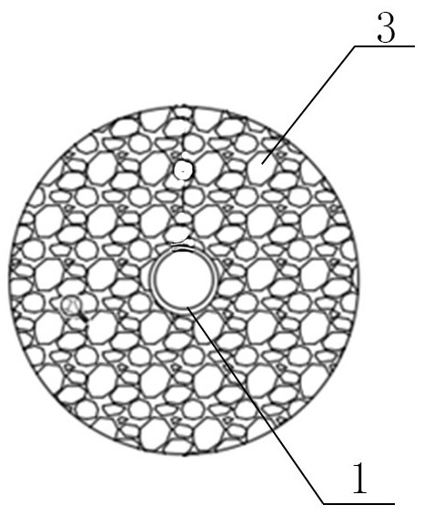
[0028] Such as Figure 1-3 As shown, this precipitation structure for preventing the underground structure from floating is used to reduce the groundwater level below the foundation floor 7; a water collection well 8 is arranged in the foundation floor 7, and a cushion layer 9 is provided at the bottom of the foundation floor 7; the precipitation The structure includes a drain pipe 1, a water stop plate 2 and a gravel filter layer 3; the drain pipe 1 is arranged at the bottom of the sump 8, and the lower end of the drain pipe 1 extends into the soil below the cushion 9; On the side wall of the drain pipe 1, a drain hole 10 is separated at a position in the soil; the inside of the drain pipe 1 is filled with an expanded concrete core 4, and the top surface of the expanded concrete core 4 is lower than the drain pipe. 1; the inside of the pipe of the drain pipe 1 is provided with a sealing plate 6 at the top surface of the expanded concrete core 4; the sealing paste 5 is filled ...


PUM

PropertyMeasurementUnit
Diameteraaaaaaaaaa
Lengthaaaaaaaaaa
Widthaaaaaaaaaa

Abstract

The invention discloses a dewatering structure for preventing an underground structure from floating upwards and a construction method thereof. The dewatering structure comprises a water drain pipe, a water stop plate and a gravel filter layer; the drain pipe is arranged at the bottom of a water-collecting well, and the lower end of the drain pipe extends into a soil body below a cushion layer; water drain hole channels are formed in the side wall of the water drain pipe and located in the soil body at intervals; a pipeline of the water drain pipe is filled with an expansive concrete core, and the top face of the expansive concrete core is lower than the top end of the water drain pipe; a plugging plate is arranged in the pipeline of the water drain pipe and located on the top face of the expansive concrete core; the water drain pipe above the plugging plate is filled with a sealant; the water stop plate is annular and is welded to the outer side wall of the water drain pipe; the periphery of the water drain pipe is filled with the gravel filtering layer, and the top face of the gravel filtering layer is flush with the bottom face of the cushion layer; and the outer side of the gravel filtering layer is wrapped with geotechnical cloth. The technical problems that a traditional bottom plate reserved dewatering pipe well is complex in construction procedure, leakage is prone to occurring in the later period, and the dewatering well is damaged or stops running in the construction period of a basement main body structure are solved.

Description

technical field [0001] The invention belongs to the technical field of building engineering construction, in particular to a precipitation structure for preventing underground structures from floating up and a construction method thereof. Background technique [0002] As the development of real estate projects accelerates, accidents caused by groundwater problems such as basement floating and floor punching damage during construction occur frequently. Such accidents are usually caused by the following reasons: 1. The precipitation well is damaged due to construction and cannot be used for precipitation; 2. 1. After the post-pouring belt is closed and the fertilizer tank of the foundation pit is backfilled, there is no precipitation measure. At the same time, the roof of the garage is not covered with soil, and the garage structure is insufficient in anti-floating; 3. The value of the anti-floating water level is wrong, and the actual water level exceeds the anti-floating desi...

Claims


Application Information

Patent Timeline
IPC IPC(8): E02D19/10E02D31/12
CPCE02D19/10E02D31/12
Inventor 吕礼春
Owner 新城控股集团实业发展有限公司
Learn More