
Well lid with rapid dredging function

A manhole cover and function technology, which is applied in waterway systems, climate change adaptation, drainage structures, etc., can solve the problems of urban road water accumulation, filter blockage, urban traffic inconvenience, etc., and achieve the effect of convenient use, good effect and simple structure.

Pending Publication Date: 2021-11-30
杨金璋
View PDF5 Cites 0 Cited by
  • Summary
  • Abstract
  • Description
  • Claims
  • Application Information

AI Technical Summary

Problems solved by technology

[0003] At present, most of the manhole covers used in sewers in cities are composed of simple filters and protective covers, and these manhole covers do not have the function of automatic dredging. There will be a certain amount of garbage mixed with rainwater. When the rainwater flows from the manhole cover into the sewer, the garbage will block the filter screen, causing large areas of urban roads to accumulate water, which brings great inconvenience to urban traffic.

Method used


Image

  • Well lid with rapid dredging function
  • Well lid with rapid dredging function
  • Well lid with rapid dredging function

Examples


Embodiment 1

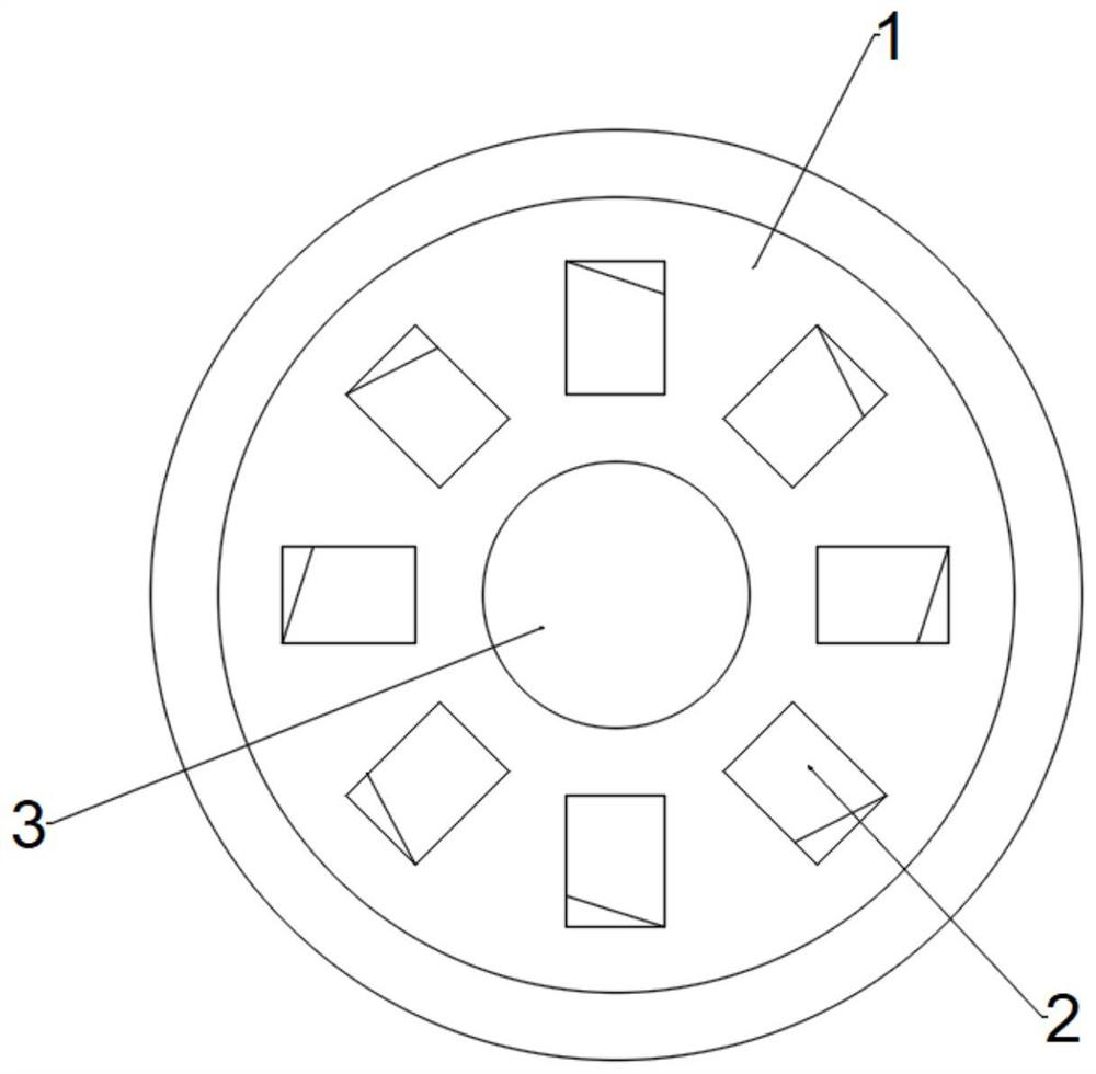
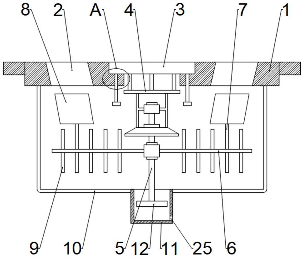
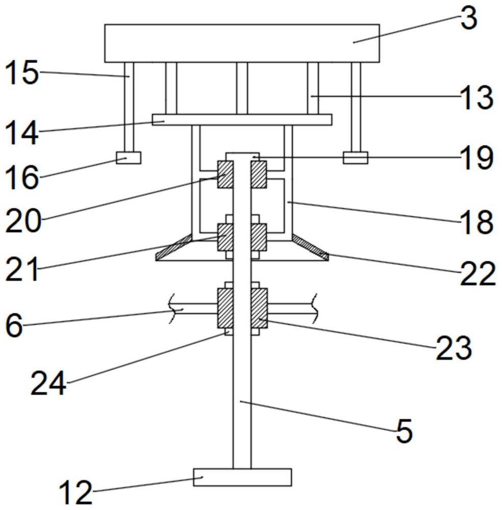
[0026] see figure 1 , 2 , A manhole cover with a quick dredging function, including a manhole cover body 1, a mounting slot hole is arranged in the center of the manhole cover body 1, a flood control plate 3 is arranged in the installation slot hole, and the periphery of the flood control plate 3 is provided with a number of along the manhole cover The drain holes 2 are symmetrically distributed in the center of the body 1. The drain holes 2 are inclined along the circumferential direction of the manhole cover body 1. One end of the flood control plate 3 is provided with a mounting frame 4, and the mounting frame 4 is provided with a rotating shaft 5. , the rotating shaft 5 can rotate freely on the mounting frame 4, the rotating shaft 5 is provided with a third connecting sleeve 23, the outer wall of the third connecting sleeve 23 is connected with a rotating rod 6, and the rotating rod 6 is provided with several A dredging rod 9 is provided, and the side of the rotating rod ...

Embodiment 2

[0032] see figure 2 , On the basis of Example 1, although the automatic dredging process can be well performed and the water flow is accelerated, but in a relatively harsh environment, such as when the water flow is too large, only the drainage hole 2 cannot effectively drain the ground water. Therefore, a flood control mechanism is also provided on the manhole cover body 1, and the flood control mechanism includes a water accumulation bucket 11 and a floating plate 12, and the water accumulation bucket 11 is connected and arranged on one side of the manhole cover body 1 through a right-angle rod 10, The end of the rotating shaft 5 away from the manhole cover body 1 is provided with a floating plate 12 , the floating plate 12 is placed in the inner cavity of the water storage bucket 11 , and the bottom of the water storage bucket 11 is provided with a fine hole 25 .

[0033] see figure 2 , 4 , in order to prevent the flood control plate 3 from accidentally falling off the ...


PUM


Abstract

The invention discloses a well lid with a rapid dredging function. The well lid comprises a well lid body, a flood control disc is arranged on the well lid body, a plurality of drainage holes inclined in the circumferential direction of the well lid body are formed in the periphery of the flood control disc, a mounting frame is arranged at one end of the flood control disc, a rotating shaft is arranged on the mounting frame, the rotating shaft is connected with a rotating rod through a third connecting sleeve, the rotating rod is provided with a plurality of dredging rods, and the side, close to the well lid body, of the rotating rod is connected with a vane plate through a vertical rod. When the well lid discharges water, the water can flow out spirally and downwards in the inclined direction of the drainage holes, in the flowing-out process, the water flow flushes towards an impeller plate and drives the impeller plate to move, the impeller plate moves to drive the rotating shaft to rotate so as to drive the dredging rods to do circular motion around the rotating shaft, so that the lower portion of the well lid is dredged, water flow power during drainage is utilized in overall dredging treatment, resources are saved, dredging treatment can be automatically completed, and use is quite convenient.

Description

technical field [0001] The invention relates to the field of manhole covers, in particular to a manhole cover with a quick dredging function. Background technique [0002] The sewer is one of the most important components of urban flood control. In order to play a role in safety and protect the environment, it is necessary to install a manhole cover on the top of the sewer. [0003] At present, manhole covers used in urban sewers are mostly composed of simple filters and protective covers, and these manhole covers do not have the function of automatic dredging. When encountering heavy rain, the water flow on the road is large, and the road There will be a certain amount of garbage mixed with rainwater. When the rainwater flows from the manhole cover to the sewer, the garbage will block the filter screen, causing a large area of ​​urban roads to accumulate water, which brings great inconvenience to urban traffic. SUMMARY OF THE INVENTION [0004] The purpose of the present...

Claims


Application Information

Patent Timeline
Patent Type & Authority Applications(China)
IPC IPC(8): E03F5/06E03F7/00
CPCE03F5/06E03F7/00Y02A30/60
Inventor 杨金璋
Owner 杨金璋
Learn More