
Evaluation method and evaluation device for operation refusing risk of circuit breaker

An evaluation method and circuit breaker technology, which is applied in circuit breaker testing, measuring devices, instruments, etc., can solve the problems of complex vibration signal or sound signal acquisition methods, harsh environmental requirements, and complicated comparison process, etc., to achieve directivity Strong, low-cost, quantity-reducing effect

Active Publication Date: 2021-11-30
北京慧智神光科技有限公司
View PDF6 Cites 0 Cited by
  • Summary
  • Abstract
  • Description
  • Claims
  • Application Information

AI Technical Summary

Problems solved by technology

However, the acquisition methods of vibration signals or sound signals are complicated, costly, and have strict requirements on the environment
Although the acquisition method of the opening and closing current curve is relatively simple and low-cost compared with the acquisition of vibration signals or sound signals, usually the waveform of the entire opening and closing current curve to be tested is compared with the opening and closing of all samples stored in the expert system. The waveform of the current curve is compared. The whole comparison process needs to compare all the feature points on the switching current curve to be tested and the switching current curves of all samples. Therefore, the whole comparison process is more complicated, and if there are insufficient samples in the expert system or The inaccurate evaluation results given for the samples will cause large errors in the final evaluation results.

Method used


Image

  • Evaluation method and evaluation device for operation refusing risk of circuit breaker
  • Evaluation method and evaluation device for operation refusing risk of circuit breaker
  • Evaluation method and evaluation device for operation refusing risk of circuit breaker

Examples


Embodiment Construction

[0029] Next, the technical solutions in the present application embodiment will be described in the present application embodiment, and it is clear that the described embodiments are intended to be described herein, not all of the embodiments of the present application. Based on the embodiments in the present application, one of ordinary skill in the art is in the scope of the present application without making creative labor premistence.

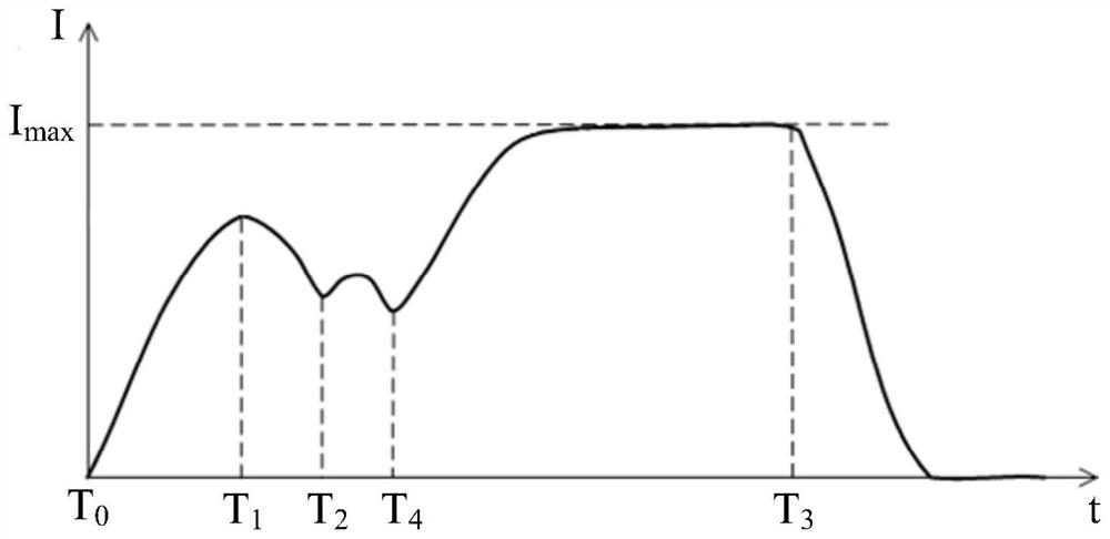
[0030] figure 1 A typical partial current curve shown as a circuit breaker is shown. like figure 1 As shown, the abscissa is time t (unit: MS) in the separation current curve, and the ordinate is current I (unit: a). The circuit breaker includes, but is not limited to, a core, a groove coil, a trip curved plate, and a trip unit, and the trip unit can be a hierarchy stripker and / or a closing throttle.

[0031] In this partial current curve, t 0 Indicates the moment at which the coordination coil is powered on, at this time, the current I is 0...


PUM


Abstract

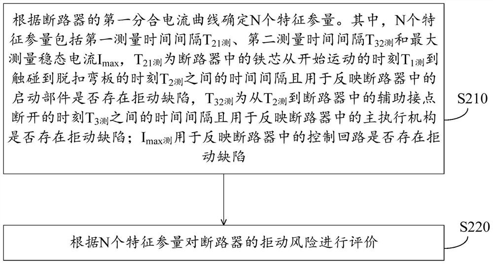
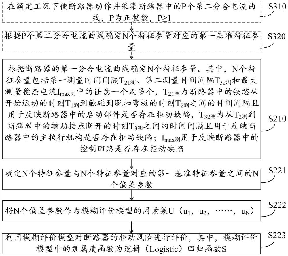
The invention provides an evaluation method and an evaluation device for the operation refusing risk of a circuit breaker. The evaluation method comprises the steps that N characteristic parameters are determined according to a first opening and closing current curve of the circuit breaker, and the N characteristic parameters comprise a first measurement time interval T21 measurement, a second measurement time interval T32 measurement and a maximum measurement steady-state current Imax measurement, T21 measurement is a time interval between a moment T1 measurement when an iron core in the circuit breaker starts to move and a moment T2 measurement when the iron core touches a tripping bending plate, and is used for reflecting whether a starting part in the circuit breaker has an action refusing defect or not; the T32 measurement is a time interval from the T2 measurement to the time T3 measurement when the auxiliary contact in the circuit breaker is switched off and is used for reflecting whether the main actuating mechanism in the circuit breaker has the action refusing defect or not; the Imax measurement is used for reflecting whether a control loop in the circuit breaker has a refusing defect or not; and the refusing risk of the circuit breaker is evaluated according to the N characteristic parameters, so that the complexity in the evaluation process can be reduced.

Description

Technical field [0001] The present application relates to the technical field of circuit breakers, and in particular to evaluation methods for the rejection risk of a circuit breaker and its evaluation device. Background technique [0002] The circuit breaker is an important device for controlling and protecting electrical in the power system. Once the circuit breaker has failed, it will directly affect the security and reliability of the entire power system. The fault type of the circuit breaker includes a refusal failure, an insulation failure, and an external force failure. Among them, the refusal failure is a type of faulty frequency, therefore, the evaluation of the rejection risk of the circuit breaker is important. [0003] Typically, the risks of the circuit breaker are evaluated based on vibration signals, sound signals, or integrated current curves. However, the collection mode of the vibration signal or sound signal is complicated, high cost, and is more demanding for ...

Claims


Application Information

Patent Timeline
Patent Type & Authority Applications(China)
IPC IPC(8): G01R31/327G06F17/18G06F30/20G06N7/02
CPCG01R31/3278G06F30/20G06F17/18G06N7/02
Inventor 刘景安黄强
Owner 北京慧智神光科技有限公司
Learn More