

Flame visual ranging self-adjusting intelligent fire extinguisher
A technology of visual ranging and fire extinguisher, applied in fire rescue and other directions, can solve the problems that the fire extinguisher cannot be fixed on the wall, the fire extinguisher cannot be visually measured, and it is inconvenient to install and disassemble. Stirring efficiency, the effect of reducing the secondary loss
- Summary
- Abstract
- Description
- Claims
- Application Information
AI Technical Summary
Problems solved by technology
Method used
Image

Examples
Embodiment Construction
[0033] The following will clearly and completely describe the technical solutions in the embodiments of the present invention with reference to the accompanying drawings in the embodiments of the present invention. Obviously, the described embodiments are only some, not all, embodiments of the present invention. Based on the embodiments of the present invention, all other embodiments obtained by persons of ordinary skill in the art without making creative efforts belong to the protection scope of the present invention.
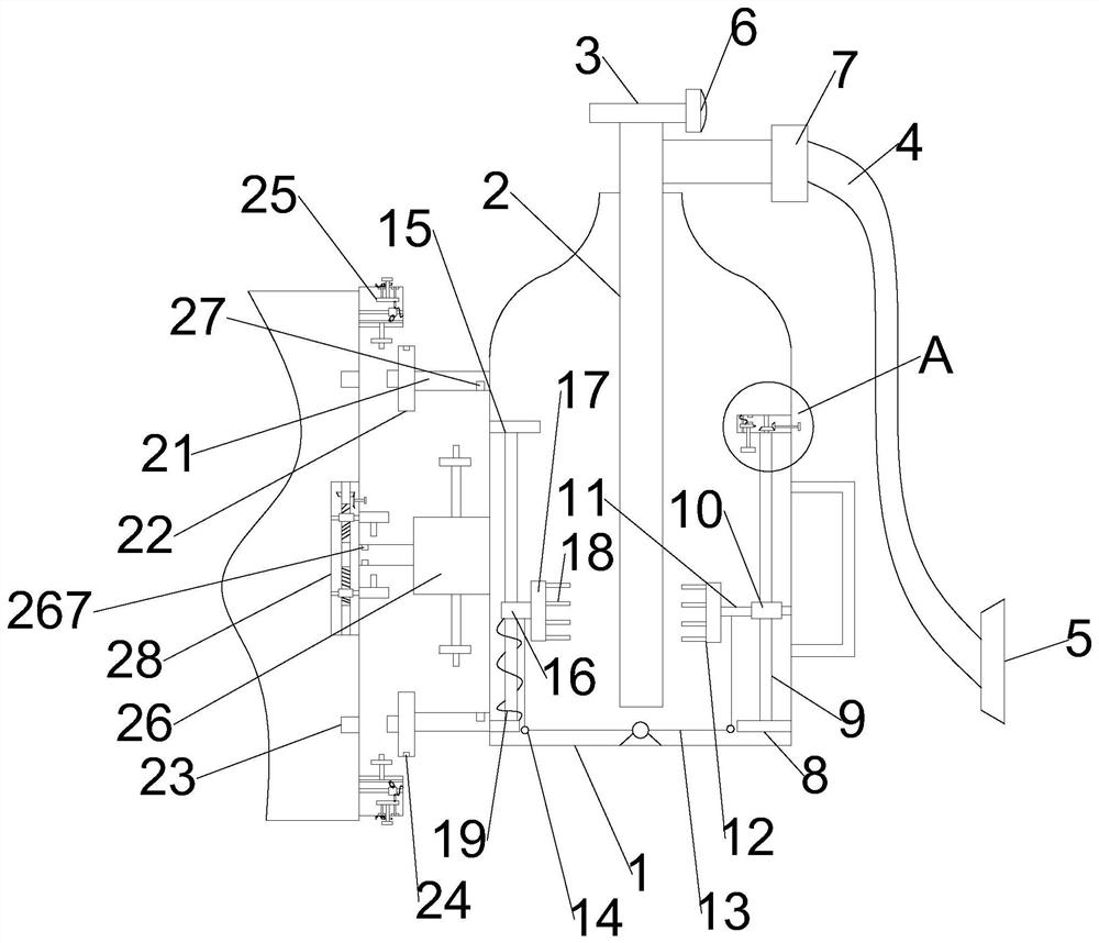
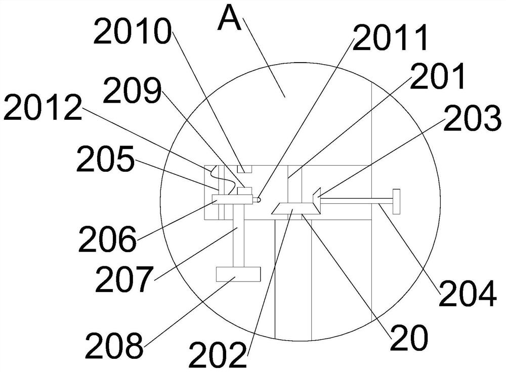
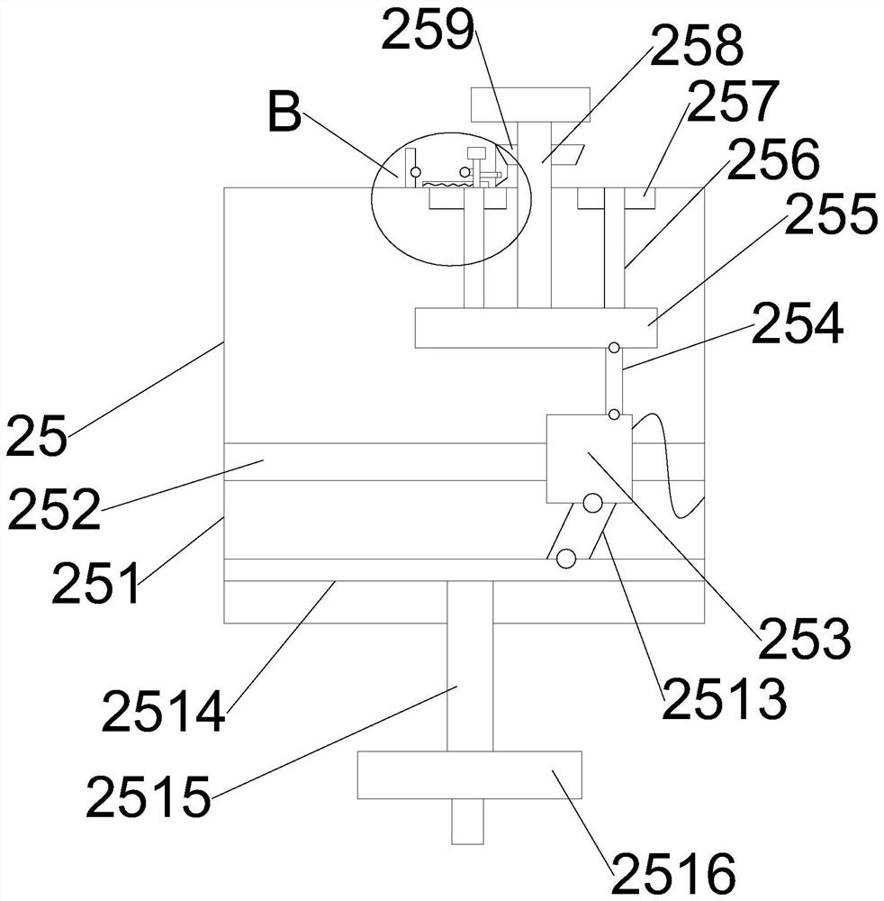
[0034] see Figure 1-8 , in the present invention, a kind of self-regulating intelligent fire extinguisher of flame visual distance measurement, comprises fire extinguisher body 1, and the side wall of fire extinguisher body 1 is provided with handle, and vent pipe 2 is installed in described fire extinguisher body 1, and the top of vent pipe 2 is provided with stop valve 3. The stop valve 3 is provided with an air spray hose 4, the air spray hose 4 is provided ...
PUM
 Abstract
Description
Claims
Application Information