A Method of Reducing the Loss of Synchronous Rectification Drive Circuit Based on Coupling Coils

A technology of synchronous rectification and drive circuit, which is applied in the direction of electrical components, high-efficiency power electronic conversion, and output power conversion devices, etc., which can solve the problems of high cost and large loss of synchronous rectification drive circuit, so as to reduce power loss and secondary side The effect of loss

Inactive Publication Date: 2017-02-08
XI'AN POLYTECHNIC UNIVERSITY
View PDF5 Cites 0 Cited by
  • Summary
  • Abstract
  • Description
  • Claims
  • Application Information

AI Technical Summary

Problems solved by technology

Among them, self-drive is divided into voltage-type self-drive and current-type self-drive according to the type of synchronous drive signal source; due to the high cost of external drive, voltage-type self-drive is affected by the range of input voltage, so it is rarely used; current-type self-drive It is an ideal synchronous rectification driving scheme, but the problem of large loss of synchronous rectification driving circuit has always been concerned

Method used


Image

  • A Method of Reducing the Loss of Synchronous Rectification Drive Circuit Based on Coupling Coils

Examples


Embodiment Construction

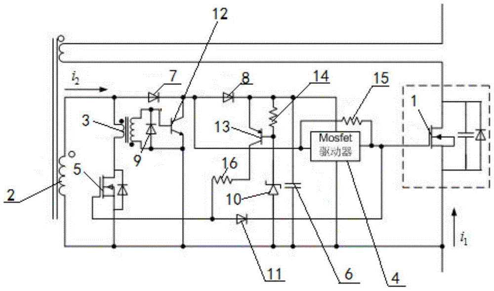
[0034] The present invention is based on the method for reducing the loss of the synchronous rectification drive circuit based on the coupling coil, such as figure 1 As shown, the specific steps are as follows:

[0035] Step 1. Build a synchronous rectification drive circuit, the specific method is as follows:

[0036] Synchronous rectification drive circuit, specifically as figure 1 as shown, figure 1 The dotted line in the box indicates the synchronous rectification Mosfet that replaces the existing rectifier diode, and the branch where it is located is the rectification branch;

[0037] Add a current transformer a2 to the rectifier branch, and the current transformer a2 to detect the current signal; connect a switch tube 5 to the secondary side of the current transformer a2, and use the principle of switching the switch tube 5 to short-circuit the secondary side to reduce synchronous rectification The loss of the drive circuit;

[0038] A current transformer b3 is added...


PUM


Abstract

The method for reducing the loss of a synchronous rectification drive circuit based on a coupling coil disclosed in the present invention, the specific method is: construct a synchronous rectification drive circuit; detect the current signal of the rectification branch, and use the detected current signal to synchronously drive the turn-on signal; wait for the synchronous rectification drive After the circuit outputs a high level, the synchronous rectification driving circuit makes the secondary side of the current transformer a short-circuit through the adjustment of the internal circuit. With the change of the rectification branch current, the voltage pulse width of the secondary side of the current transformer a is adaptively adjusted to Optimum state: use the relationship between the excitation current and the secondary current of the current transformer a to turn off the synchronous rectifier. The method for reducing the loss of the synchronous rectification drive circuit based on the coupling coil of the present invention has the characteristics of low power consumption, good versatility, and can work in current discontinuous and continuous modes.

Description

technical field [0001] The invention belongs to the technical field of power circuit application methods, and relates to a method for reducing the loss of a synchronous rectification drive circuit based on a coupled coil. Background technique [0002] With the rapid development of electronic technology, people are becoming more and more dependent on electronic devices. In order to facilitate people to carry electronic products when traveling, more and more portable electronic products, such as mobile phones and tablet computers, have appeared. [0003] Nowadays, the volume of portable electronic products is getting smaller and smaller. In order to ensure the safety of electronic products, the power supply voltage requirements are lower and lower. Under a certain power, the current requirements are higher; however, the increase in current will bring A very serious problem is that the efficiency of the switching converter is low due to the large on-state loss caused by diode r...

Claims


Application Information

Patent Timeline
Patent Type & Authority Patents(China)
IPC IPC(8): H02M7/217
CPCH02M7/217H02M1/0048Y02B70/10
Inventor 陈增禄方日张俊奇曹立航胡秀芳
Owner XI'AN POLYTECHNIC UNIVERSITY
Why Eureka
Try Eureka