
Real-time cleaning device for oil-gas pipeline of tire oil refining reaction kettle

A technology for cleaning devices and oil and gas pipelines, applied in the petroleum industry, cleaning hollow objects, chemical/physical processes, etc., can solve problems such as adhesion, affecting pipeline flow, and the inner wall of the pipeline cannot be cleaned in real time, so as to achieve ingenious structure and ensure flow area effect

Inactive Publication Date: 2021-12-03
程梦阳
View PDF8 Cites 0 Cited by
  • Summary
  • Abstract
  • Description
  • Claims
  • Application Information

AI Technical Summary

Problems solved by technology

[0003] In view of the above situation, in order to overcome the defects of the prior art, the present invention provides a real-time cleaning device for the oil and gas pipeline of the tire refinery reactor, which effectively solves the problem that the inner wall of the pipeline transporting high-temperature oil and gas cannot be cleaned in real time in the prior art, and it is easy to get stuck on the inner wall of the pipeline. Adhesion to the top, seriously affecting the flow of the pipeline

Method used


Image

  • Real-time cleaning device for oil-gas pipeline of tire oil refining reaction kettle
  • Real-time cleaning device for oil-gas pipeline of tire oil refining reaction kettle
  • Real-time cleaning device for oil-gas pipeline of tire oil refining reaction kettle

Examples


Embodiment Construction

[0019] The specific implementation manners of the present invention will be further described in detail below in conjunction with the accompanying drawings.

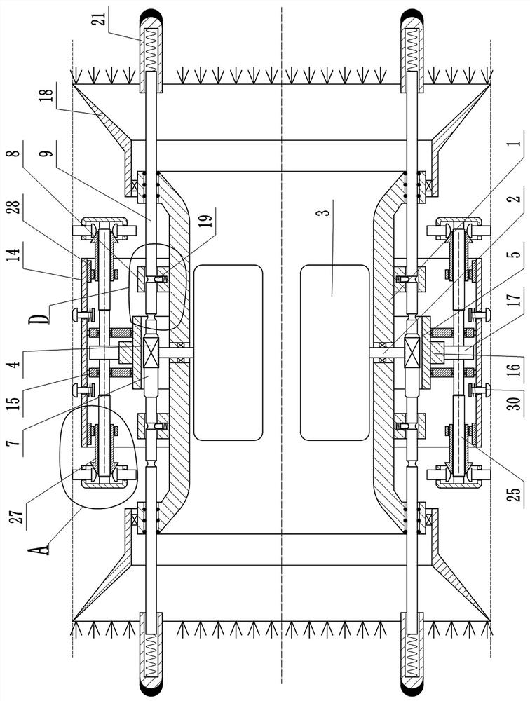
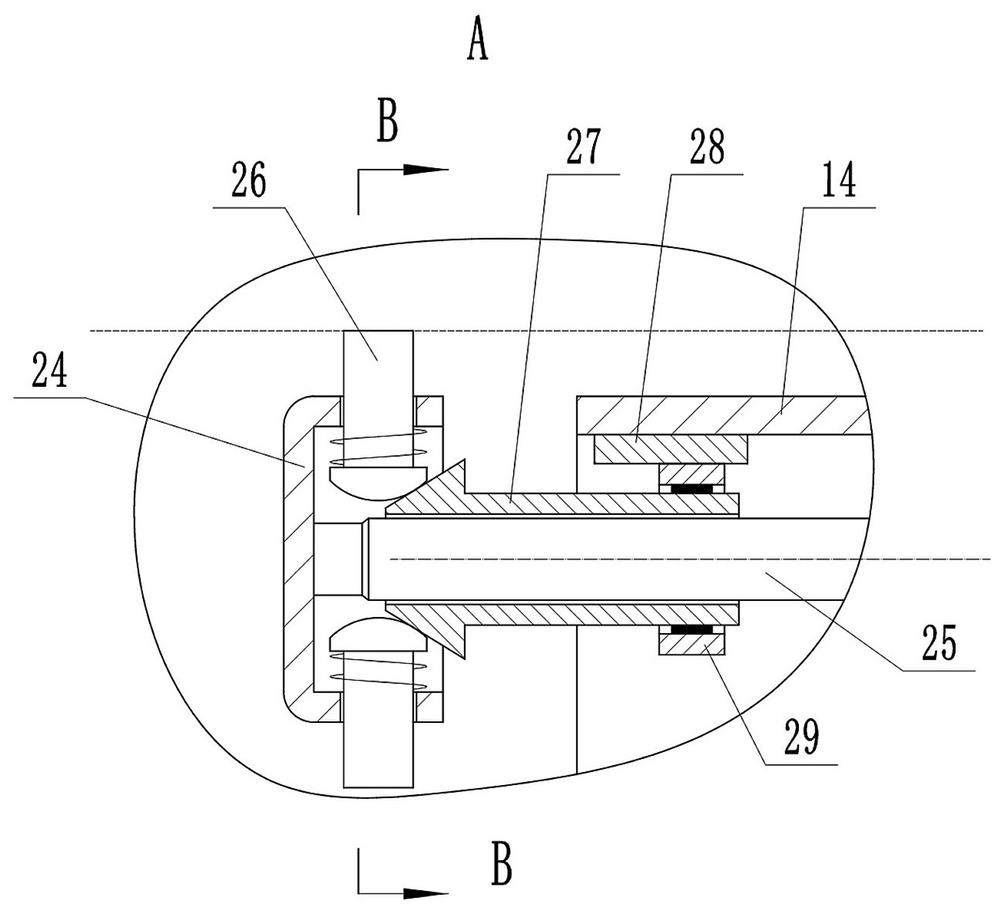
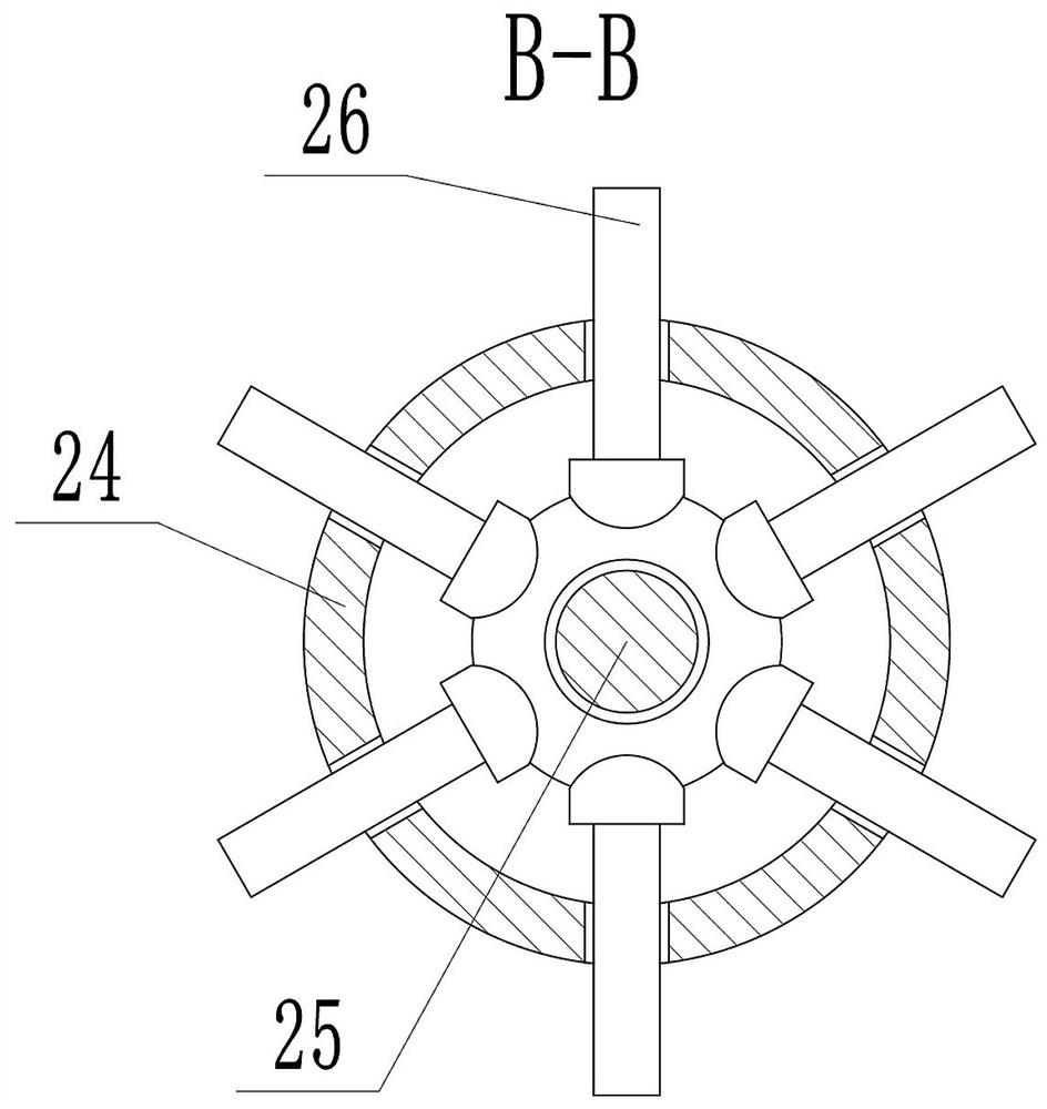
[0020] Depend on Figure 1 to Figure 7 Provided, the present invention comprises a horizontal hollow cylinder 1, a plurality of rotatable rotating shafts 2 run through the side wall of the hollow cylinder 1, and the plurality of rotating shafts 2 are uniformly distributed on the circumference, and there are a plurality of flat plates 3 in the hollow cylinder 1, and the flat plates 3 and The rotating shafts 2 are fixed together in one-to-one correspondence. There is a first gear 4 corresponding to the rotating shaft 2 on the outside of the hollow cylinder 1. The first gear 4 is coaxially fixed with the rotating shaft 2. One side of the first gear 4 is meshed with a Axially arranged rack 7, rack 7 can move left and right, and rack 7 can drive plate 3 to rotate around shaft 2 through first gear 4. There are multiple rectang...


PUM


Abstract

The invention provides a real-time cleaning device for an oil-gas pipeline of a tire oil refining reaction kettle, and effectively solves the problems that in the prior art, the inner wall of a pipeline for conveying high-temperature oil gas cannot be cleaned in real time, attachment to the inner wall of the pipeline is easily caused, and the through-flow of the pipeline is seriously influenced. According to the technical scheme, the device comprises a hollow cylinder, a plurality of rotating shafts penetrate through the side wall of the hollow cylinder, a plurality of flat plates are arranged in the hollow cylinder, a first gear is arranged on the outer side of the hollow cylinder, the first gear is provided with a rack, a plurality of rectangular blocks are arranged on the outer side of the hollow cylinder, and a cross rod is arranged at the end of the rack; an annular cylinder is arranged on the outer side of the hollow cylinder and fixed to the hollow cylinder. The outer side of the annular cylinder is sleeved with an outer cylinder, two annular plates are arranged between the outer cylinder and the annular cylinder, an outer gear ring is fixed to the outer side of the annular cylinder, a plurality of transmission gears are arranged between the two annular plates, the transmission gears and the outer gear ring are in transmission through staggered shaft bevel gears, and wheels are fixed to the two ends of a center shaft of each transmission gear. Two ends of the hollow cylinder are connected with conical cylinders through bearings.

Description

technical field [0001] The invention relates to the technical field of tire refining, in particular to a real-time cleaning device for oil and gas pipelines of a tire refining reactor. Background technique [0002] Rotary kiln pyrolysis technology is used to prepare fuel oil from waste tires, which is more extensive than other technologies. In the pyrolysis process, waste tires are put into the pyrolysis axe, heated up, dehydrated, and then heated up, the tires are melted and then gasified, and liquid tire oil can be obtained through condensation in a condenser and separation in a separator. Among them, tire gasification produces oil gas and light carbon black, which are transported from the outlet of the reactor to the dust removal equipment through the pipeline. In this pipeline, because the gas contains a large amount of carbon black, the carbon black is easy to gather and form agglomerates on the inner wall of the pipeline. After a long time, it will seriously affect th...

Claims


Application Information

Patent Timeline
Patent Type & Authority Applications(China)
IPC IPC(8): B01J19/00B08B9/032C10G1/10
CPCB01J19/0053C10G1/10B08B9/0321
Inventor 程梦阳
Owner 程梦阳
Learn More