Metal plate surface wire drawing machining equipment

A surface drawing and processing equipment technology, applied in metal processing equipment, grinding/polishing equipment, manufacturing tools, etc., can solve the problems of easy inclination, easy shaking, and lack of stability of metal plates in drawing, and achieve enhanced fixing effect , enhance the effect of drawing, and facilitate the effect of drawing treatment

Active Publication Date: 2021-12-03
CHUZHOU UNIV
View PDF10 Cites 3 Cited by
  • Summary
  • Abstract
  • Description
  • Claims
  • Application Information

AI Technical Summary

Problems solved by technology

[0003] However, there are the following problems in wire drawing processing of metal sheets at present: 1. Most of the general wire drawing equipment is to carry out conveyor belt type wire drawing processing on metal sheets, because the conveyor belt of this type of equipment cannot fix the metal sheet, so the metal sheet is The lack of stability in the wire drawing process makes the metal sheet easy to shake during the wire drawing process, so that the wire drawing on the surface of the metal sheet is prone to tilting
[0004] 2. Most of the existing wire drawing equipment is for single-sided wire drawing of metal sheets, so it is necessary to turn over the metal sheet and then perform wire drawing again, thereby increasing the workload and affecting the wire drawing effect of the metal sheet

Method used


Image

  • Metal plate surface wire drawing machining equipment
  • Metal plate surface wire drawing machining equipment
  • Metal plate surface wire drawing machining equipment

Examples


Embodiment Construction

[0031] The embodiments of the present invention will be described in detail below with reference to the accompanying drawings, but the present invention can be implemented in many different ways defined and covered by the claims.

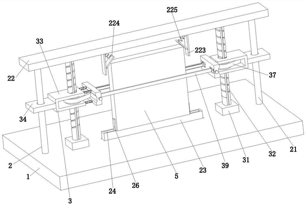
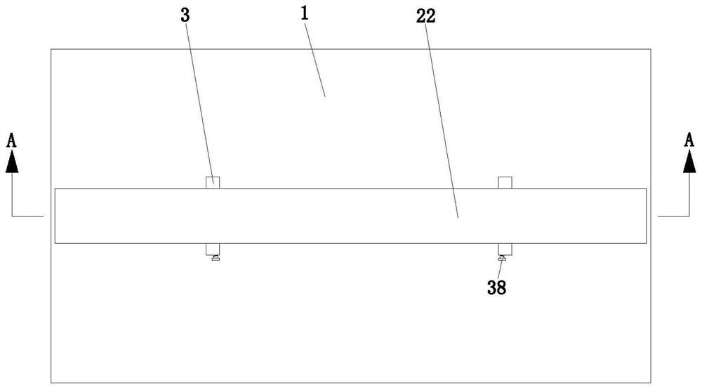
[0032] refer to figure 1 , a metal plate surface drawing processing equipment, including a base 1, a fixing unit 2 and a drawing unit 3, the upper end of the base 1 is provided with a fixing unit 2, and the drawing unit 3 is installed on the base 1 and the fixing unit 2.

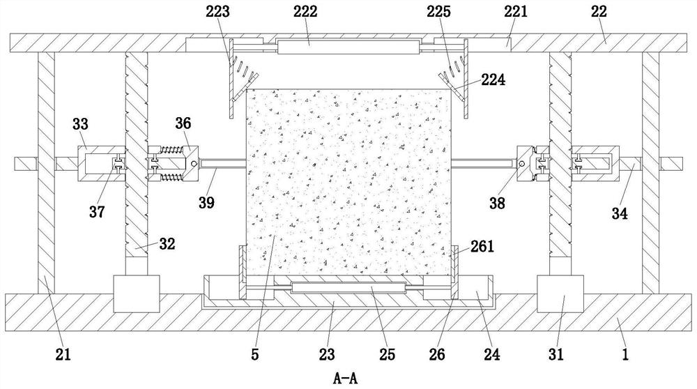
[0033] refer to figure 1 , image 3 , the fixed unit 2 includes a fixed rod 21, a supporting plate 22, a support block 23, a linkage groove 24, a No. 1 two-way cylinder 25 and a clamping plate 26, wherein: the fixed rod 21 is symmetrically installed on the upper end of the base 1, fixed One end of the rod 21 away from the base 1 is fixedly provided with a support plate 22, a support block 23 is mounted on the upper end of the base 1, and the upper end of the support block 23 is ...


PUM


Abstract

The invention relates to the technical field of metal plate machining, in particular to metal plate surface wire drawing machining equipment. The metal plate surface wire drawing machining equipment comprises a base, a fixing unit and a wire drawing unit, wherein the fixing unit is arranged at the upper end of the base, and the wire drawing unit is installed on the base and the fixing unit. The metal plate surface wire drawing machining equipment can solve the following problems that common wire drawing equipment cannot fix metal plates, therefore, the metal plates are lack of stability in the wire drawing process; and most existing wire drawing equipment is used for conducting single-face wire drawing treatment on the metal plates, therefore, the metal plates need to be turned over to be subjected to wire drawing treatment again, and the workload is increased. By means of the metal plate surface wire drawing machining equipment, the metal plates can be clamped and fixed, and the stability of the metal plates in the wire drawing process can be improved; and left-right reciprocating wire drawing treatment can be synchronously conducted on the two sides of the metal plates, and wire drawing treatment can be conducted on the metal plates with different thicknesses, so that the wire drawing effect on the metal plates can be enhanced.

Description

technical field [0001] The invention relates to the technical field of metal plate processing, in particular to a wire drawing processing equipment for the surface of metal plates. Background technique [0002] Metal sheets mainly refer to metal sheets formed by forging, rolling or casting. Generally, in order to improve the surface quality of metal sheets and cover slight scratches on the surface, it is necessary to perform wire drawing on the surface of metal sheets. Wire drawing is a kind of metal surface processing. craft. Wire drawing is a method that uses the reciprocating motion of the drawing sandpaper to rub back and forth on the surface of the workpiece to improve the surface finish of the workpiece. [0003] However, there are currently the following problems in wire drawing processing of metal sheets: 1. Most of the general wire drawing equipment is used for conveyor belt-type wire drawing processing of metal sheets. Since the conveyor belt of this type of equip...

Claims


Application Information

Patent Timeline
Patent Type & Authority Applications(China)
IPC IPC(8): B24B7/10B24B41/04B24B41/06B24B47/04B24B47/22
CPCB24B7/10B24B41/06B24B47/22B24B41/04B24B47/04
Inventor 崔淑卿朱逸峰任邦彦张恩玲
Owner CHUZHOU UNIV
Why Eureka
Try Eureka