Remote monitoring system

A remote monitoring and detector technology, applied in signal transmission systems, boot programs, program control devices, etc., can solve the problems of occasional communication interruption between the device and the monitoring center, and the inability to accurately know the operating status of the monitoring device, so as to save battery power. Effect

Pending Publication Date: 2021-12-03
UNDERGROUND SYST
View PDF0 Cites 2 Cited by
  • Summary
  • Abstract
  • Description
  • Claims
  • Application Information

AI Technical Summary

Problems solved by technology

[0007] Also, while for remotely located subsurface monitoring installations, interruptions in the power supplied to the installation are not uncommon, more likely are occasional communication interruption

Method used


Image

  • Remote monitoring system
  • Remote monitoring system
  • Remote monitoring system

Examples


Embodiment Construction

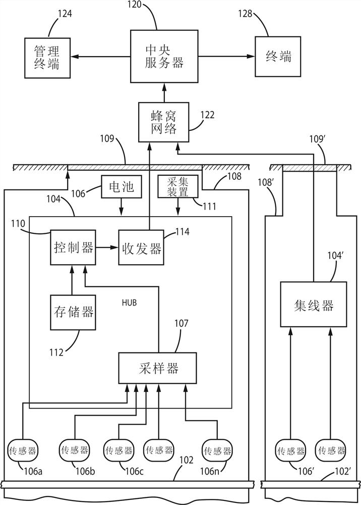
[0023] With reference to the accompanying drawings, figure 1 is a block diagram of one embodiment of the remote monitoring system according to the present invention. Therein, a hub 104 disposed in an underground cable closet 108 monitors parameters of the underground asset 102; processes and sends data derived from the monitored parameters to a central location 120, eg, a central server. Optionally, the hub can be installed below grade in a curb box or hand hole. In this embodiment, the hub 104 includes a sampler 107 coupled to the sensors 106a, 106b, . . . , 106n for sampling signals generated by the sensors. Sensors are distributed external to the hub and are adapted to generate signals indicative of detected or sensed parameters of the subsurface asset, such as temperature, pressure, voltage, current, and the like. Sensors can be simple wire connectors or more complex transducers. Assets can be electrical cables, pipelines carrying oil, gas, water, or other pipelines, ac...


PUM


Abstract

A remote monitoring system for monitoring parameters of an underground asset, such as an electric cable system, a pipeline serving as a conduit for water, gas, oil, sewage, or the like. Parameter detectors, such as sensors that measure temperature, voltage, current, moisture, etc., are distributed along the asset to provide electrical signals that represent respective monitored parameters of the asset. An underground hub disposed in an underground vault, or manhole, through which the asset passes is coupled to the parameter detectors to acquire the signals provided by the parameter detectors. The hub includes a controller to provide data derived from the acquired signals, the data being transmitted to a remote central location by a transceiver, or modem, via LP-WAN communication. Signals from the transceiver are transmitted directly from underground.

Description

[0001] This invention was made with US Government support under DE-SC0004280 funded by the US Department of Energy. The US Government has certain rights in this invention. technical field [0002] The present invention generally relates to monitoring systems for monitoring parameters of underground assets (eg, underground cable systems, pipelines, water pipes, sewer lines). Background technique [0003] In the field of underground power cables, water pipelines, oil and gas pipelines, sewage lines, etc. commonly referred to as subsurface assets, monitoring the operational and / or environmental conditions of these assets is of great interest. Unexpected or abnormal behavior conditions may indicate a future hazard or malfunction condition. Once these conditions are noted for subsurface assets, maintenance can be accelerated or remedial action can be taken; in turn, subsurface assets can be prevented from being inoperative or offline for longer periods of time. [0004] Monitor...

Claims


Application Information

Patent Timeline
IPC IPC(8): G01R31/08G06F17/18G08B27/00H04W76/19
CPCG01R31/083G08B21/18G08B25/10G08B29/181G08B25/007H04Q9/00H04Q2209/43H04Q2209/826H04Q2209/883G08C17/02G06F17/18G06F9/4401G08B26/007G08B27/005H04W76/19
Inventor 罗伯特·F·史密斯查尔斯·J·IV·威尔斯邓肯·坎贝尔·布里斯保罗·A·亚历克斯
Owner UNDERGROUND SYST
Why Eureka
Try Eureka