Tunnel construction water mist dust fall system based on BIM technology
A technology of tunnel construction and water mist, which is applied in the direction of membrane technology, dust prevention, and the use of liquid separation agents, etc., which can solve problems such as large dust
- Summary
- Abstract
- Description
- Claims
- Application Information
AI Technical Summary
Problems solved by technology
Method used
Image

Examples
Embodiment 1
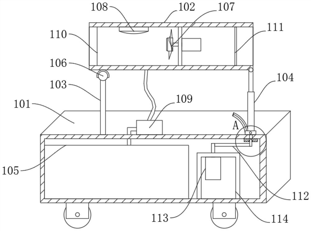
[0034] This embodiment discloses a water mist and dust suppression system for tunnel construction based on BIM technology, which includes a vehicle body 101, an air duct 102, a support column 103, a first drive assembly 104, and a water tank 105. The water tank 105 is arranged in the vehicle body 101 to support The column 103 is installed on the vehicle body 101, the upper end of the supporting column 103 is connected to the left end of the air cylinder 102 through a spherical hinge 106, and the first drive assembly 104 is installed on the vehicle body 101 to drive the air cylinder 102 to rotate around the spherical hinge 106;
[0035] The fan 107 is installed inside the air cylinder 102 by a support frame, the top of the air cylinder 102 is provided with a water mist distributor 108, the car body 101 is provided with a water mist generator 109, and the water mist generator 109 is connected with the water tank 105. The mist distributor 108 is connected with the water mist distr...
Embodiment 2
[0044] This embodiment is further optimized on the basis of Embodiment 1. In this embodiment, the support column 103 is a support rod with telescopic function.
[0045] In this way, the purpose of increasing the angle range by controlling the length of the support rod and the telescopic rod is more convenient in actual use.
Embodiment 3
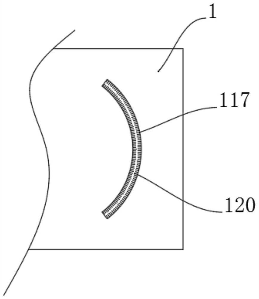
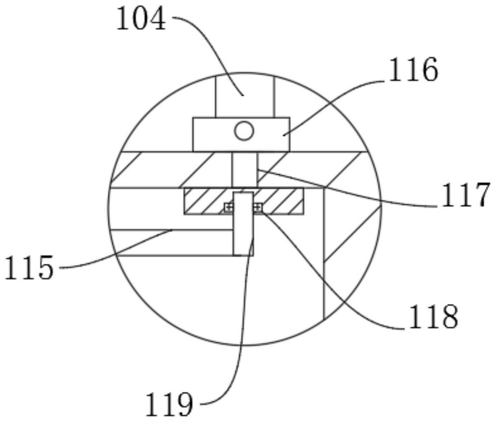
[0047] see Figure 1-Figure 3 , this embodiment is further optimized on the basis of Embodiment 1 or Embodiment 2. In this embodiment, a second drive assembly 112 is connected below the telescopic rod, and the second drive assembly 112 includes a motor 113, a mounting frame 114, Driving rod 115 and sliding seat 116, car body 101 is provided with arc groove 117, and motor 113 is fixedly installed in car body 101 by mounting frame 114, and driving rod 115 is connected with the output end of motor 113, and sliding seat 116 is slidably arranged on In the arc-shaped groove 117 , the lower end of the telescopic rod is hinged with the sliding seat 116 , and the driving rod 115 is rotationally connected with the bottom of the sliding seat 116 through a driving shaft 119 .
[0048] Wherein, the drive shaft 119 is rotationally connected with the sliding seat 116 through a bearing 118 .
[0049] In this way, in actual use, the motor 113 is used to drive the drive rod 115 to rotate so th...
PUM
 Abstract
Description
Claims
Application Information
 - R&D
- Intellectual Property
- Life Sciences
- Materials
- Tech Scout
- Unparalleled Data Quality
- Higher Quality Content
- 60% Fewer Hallucinations
Browse by: Latest US Patents, China's latest patents, Technical Efficacy Thesaurus, Application Domain, Technology Topic, Popular Technical Reports.
© 2025 PatSnap. All rights reserved.Legal|Privacy policy|Modern Slavery Act Transparency Statement|Sitemap|About US| Contact US: help@patsnap.com