Conveying device for mine

A transmission device and mine technology, applied in the transmission field, can solve the problems of increasing labor costs, endangering life and health, easily causing haze, etc., and achieving the effects of increasing labor costs, preventing manual cleaning, and reducing production efficiency

Inactive Publication Date: 2021-06-29
彭伟平
View PDF0 Cites 2 Cited by
  • Summary
  • Abstract
  • Description
  • Claims
  • Application Information

AI Technical Summary

Problems solved by technology

[0002] With the development of society, the utilization of resources has become more and more perfect. Among them, the mining of mines has gradually realized automation and modularization. In the mining of mines, it is often necessary to use conveyor belts to mine ores. A large amount of dust will be generated. If the dust is not treated, the dust will enter the surrounding atmosphere, which will easily cause extreme weather such as smog, and at the same time endanger human life and health. In the process of transporting ore, small particles in the ore are easy to adhere to the conveyor belt. In fact, after a long time of use, the conveyor belt needs to be cleaned manually, which increases the labor cost and reduces the production efficiency. In order to solve these problems, a new type of mine transmission device is designed.

Method used


Image

  • Conveying device for mine
  • Conveying device for mine
  • Conveying device for mine

Examples


Embodiment Construction

[0020] The following will clearly and completely describe the technical solutions in the embodiments of the present invention with reference to the accompanying drawings in the embodiments of the present invention. Obviously, the described embodiments are only some, not all, embodiments of the present invention. Based on the embodiments of the present invention, all other embodiments obtained by persons of ordinary skill in the art without making creative efforts belong to the protection scope of the present invention.

[0021] In addition, an element in the present invention is said to be "fixed" or "disposed on" another element, and it may be directly on another element or an intervening element may also exist. When an element is referred to as being "connected to" another element, it can be directly connected to the other element or intervening elements may also be present. The terms "vertical," "horizontal," "left," "right," and similar expressions are used herein for purp...


PUM


Abstract

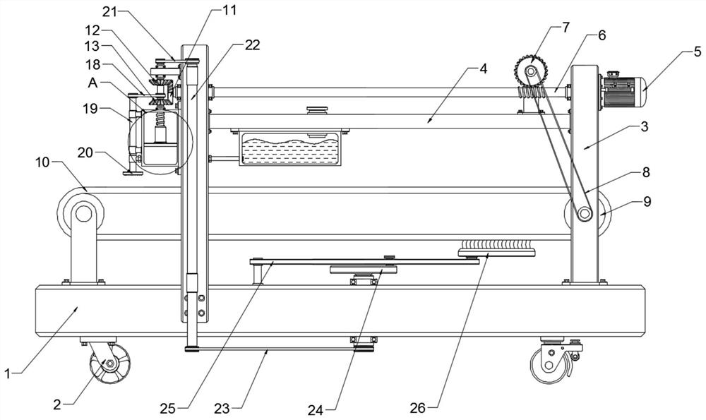
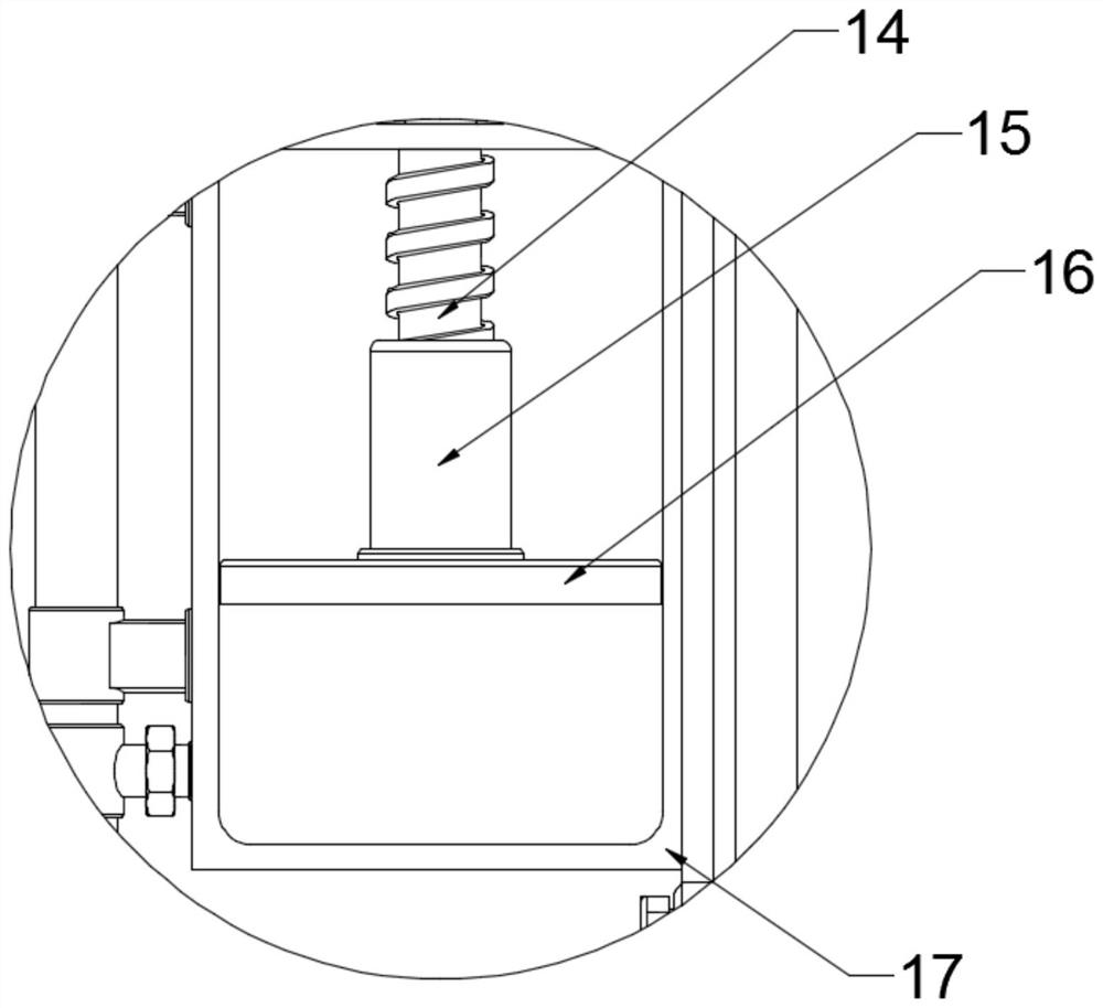
The invention relates to a conveying device for a mine. The conveying device for the mine comprises a working table and two mounting plates arranged on the working table; a transverse plate is arranged on the mounting plates; a motor is further arranged on the mounting plates; the motor is connected with two rollers arranged on the working table through a first transmission assembly; a conveying belt is arranged on the rollers; the first transmission assembly is connected with a forward and reverse rotation assembly; the forward and reverse rotation assembly is connected with a lead screw; the lead screw is in threaded fit with a threaded sleeve; one end of the threaded sleeve is connected with a hydraulic assembly arranged on the mounting plate; one side of the hydraulic assembly is connected with a water tank fixedly arranged on the transverse plate through a one-way valve; the other side of the hydraulic assembly is connected with a rotary spraying assembly, which is connected with the lead screw through a second belt and arranged on the hydraulic assembly, through the one-way valve; the lead screw is connected with a swing assembly; and a brush plate used for cleaning the conveying belt is arranged on the swing assembly. The conveying device for the mine disclosed by the invention is novel in design, simple in structure and high in practicability.

Description

technical field [0001] The invention relates to the field of transmission, in particular to a transmission device for mines. Background technique [0002] With the development of society, the utilization of resources has become more and more perfect. Among them, the mining of mines has gradually realized automation and modularization. In the mining of mines, it is often necessary to use conveyor belts to mine ores. A large amount of dust will be generated. If the dust is not treated, the dust will enter the surrounding atmosphere, which will easily cause extreme weather such as smog, and at the same time endanger human life and health. In the process of transporting ore, small particles in the ore are easy to adhere to the conveyor belt. In fact, the conveyor belt needs to be cleaned manually after being used for a long time, which increases the labor cost and reduces the production efficiency. In order to solve these problems, a new type of mine transmission device is desig...

Claims


Application Information

Patent Timeline
Patent Type & Authority Applications(China)
IPC IPC(8): B65G15/30B65G23/04B65G23/22B65G45/12B65G45/18B65G45/24B65G69/18B01D47/06
CPCB01D47/06B65G15/30B65G23/04B65G23/22B65G45/12B65G45/18B65G45/24B65G69/188
Inventor 彭伟平
Owner 彭伟平
Why Eureka
Try Eureka