Laser cutting-based plate cutting equipment

A technology of laser cutting and cutting equipment, applied in laser welding equipment, welding equipment, metal processing equipment, etc., can solve problems such as difficult to remove, difficult to quickly reduce high temperature, etc., to achieve the effect of avoiding safety hazards and rapid cooling

Inactive Publication Date: 2021-12-07
张家港市棋瑞德机械制造有限公司
View PDF11 Cites 7 Cited by
  • Summary
  • Abstract
  • Description
  • Claims
  • Application Information

AI Technical Summary

Problems solved by technology

[0003] At present, in the process of cutting the metal sheet, the laser melts the metal sheet, and the molten metal will form slag, which will adhere to the edge of the metal cutting material and the carrier of the metal sheet, which is difficult to remove, and the metal is not cut in time The material is separated, the high temperature between the metal cutting materials is difficult to drop quickly, and the metal slag will bond the cut metal together again;

Method used


Image

  • Laser cutting-based plate cutting equipment
  • Laser cutting-based plate cutting equipment
  • Laser cutting-based plate cutting equipment

Examples


Embodiment 1

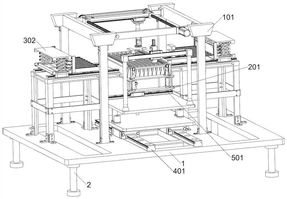
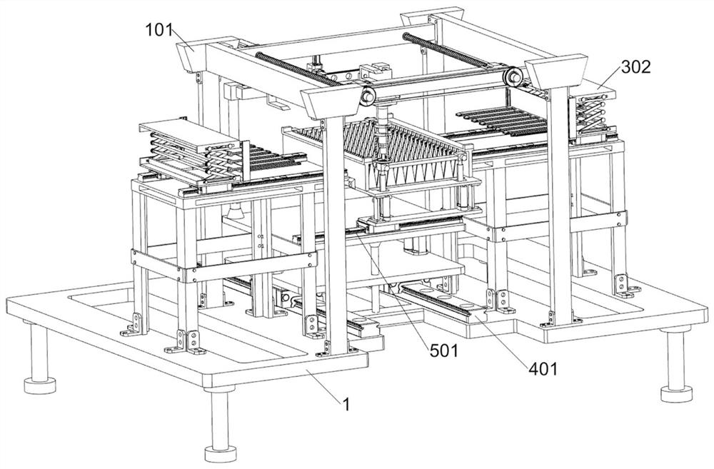
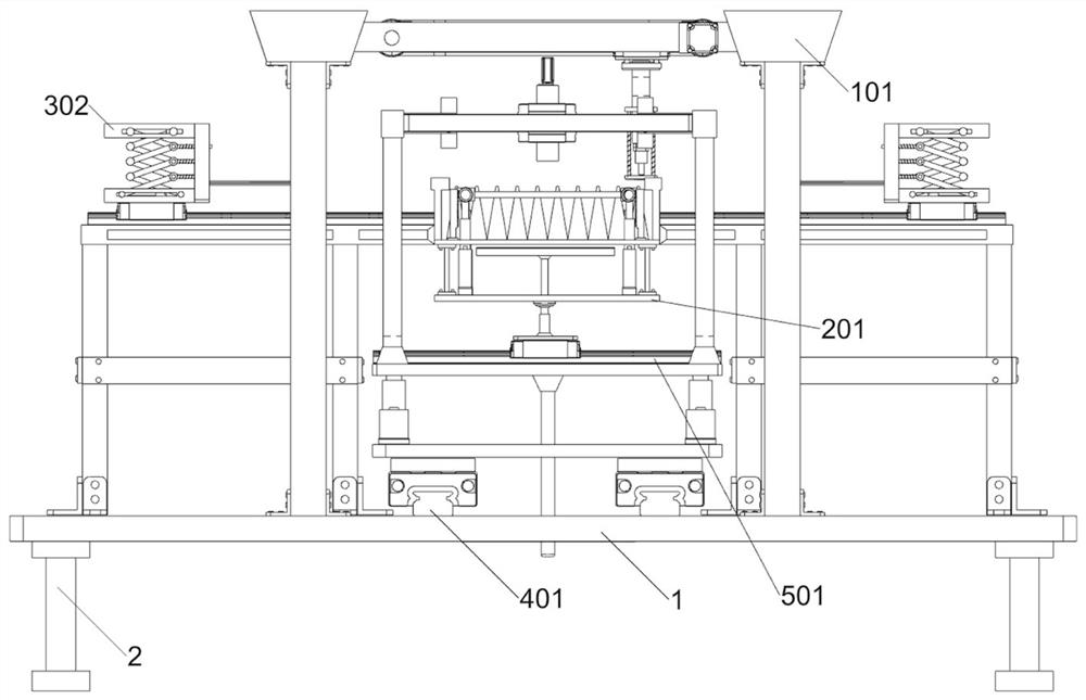
[0038] A sheet cutting equipment based on laser cutting, such as Figure 1-3 As shown, it includes a laser cutting unit, a self-cleaning support unit, a layered expansion unit, a chassis 1 and a base 2; the top of the four bases 2 is fixed with the chassis 1; the upper surface of the chassis 1 is connected with a laser cutting unit; the left and right parts of the laser cutting unit are connected with a layered expansion unit; the middle part of the laser cutting unit is connected with a self-cleaning support unit.

[0039] When using laser cutting-based plate cutting equipment, hereinafter referred to as cutting equipment, firstly, the bottom frame 1 is placed on a stable position through four bases 2, and then the cutting equipment is connected to an external power supply, and the operator puts the multi-layer metal to be processed The plate is placed in the working position of the laser cutting unit, and then the laser cutting unit starts to operate. The laser cutting unit ...

Embodiment 2

[0041] On the basis of Example 1, such as figure 1 and Figure 4-11 As shown, the laser cutting unit includes a first gantry 101, a second gantry 102, a first horizontal plate 103, a second horizontal plate 104, a first power assembly 105, a screw rod 106, a transmission wheel 107, a connecting slide Block 108, first electric slide rail 109, laser cutter 1010, first elastic member 1011, protective member 1012, bracket 1013, first mounting plate 1014, staple frame 1015 and support member 1016; bottom frame 1 upper surface right A first gantry 101 is connected to the upper part by bolts; a second gantry 102 is connected to the left part of the upper surface of the chassis 1 by bolts; The horizontal plate 103; the second horizontal plate 104 is fixedly connected to the rear of the opposite side of the first gantry 101 and the second gantry 102; the first power assembly 105 is installed on the right side of the front side of the first horizontal plate 103; the first horizontal B...

Embodiment 3

[0050] On the basis of Example 2, such as figure 1 and Figure 12-14As shown, it also includes a swinging slag removal unit, which is connected to the middle part of the upper surface of the chassis 1, and the swinging slag removal unit is located inside the laser cutting unit; the swinging slag removal unit includes a third electric slide rail 401, a second Mounting plate 402, second electric actuator 403, third mounting plate 404, pole 405, fourth electric slide rail 406, second L-shaped plate 407, E-shaped frame 408, second U-shaped frame 409, second power Assembly 4010, transmission rod 4011, cleaning part 4012 and balance bar 4013; two symmetrical third electric slide rails 401 are installed in the middle of the upper surface of the chassis 1; the two third electric slide rails 401 are connected by a second installation Plate 402; a second electric actuator 403 is installed on the left part of the upper surface and the right part of the upper surface of the second mounti...


PUM


Abstract

The invention relates to the field of laser cutting, in particular to laser cutting-based plate cutting equipment. The technical problems that a metal plate is molten through laser, molten metal can form molten slag, the molten slag can be attached to the edge of a metal cutting material and a bearing object of the metal plate and is difficult to remove, the high temperature of the metal cutting material is difficult to decrease rapidly, and the metal slag can bond the cut metal together again are solved. According to the technical scheme, the laser cutting-based plate cutting equipment comprises a bottom frame, a laser cutting unit and the like, wherein the upper surface of the bottom frame is connected with the laser cutting unit used for conducting laser cutting on the metal plate. According to the laser cutting-based plate cutting equipment, multiple layers of metal plates can be cut at the same time, and meanwhile, the situation that metal cutting materials of all layers are bonded together through slag generated after cutting can be effectively avoided.

Description

technical field [0001] The invention relates to the field of laser cutting, in particular to a plate cutting device based on laser cutting. Background technique [0002] Laser cutting is the use of high-power-density laser beams to irradiate the material to be cut, so that the material is quickly heated to melt, and as the beam moves, a narrow slit is formed on the material to complete the cutting of the material; [0003] At present, in the process of cutting the metal sheet, the laser melts the metal sheet, and the molten metal will form slag, which will adhere to the edge of the metal cutting material and the carrier of the metal sheet, which is difficult to remove, and the metal is not cut in time The material is separated, the high temperature between the metal cutting materials is difficult to drop quickly, and the metal slag will bond the cut metal together again; [0004] According to the above situation, it is necessary to develop a plate cutting equipment based on...

Claims


Application Information

Patent Timeline
Patent Type & Authority Applications(China)
IPC IPC(8): B23K26/38B23K26/70B23K26/00B23K26/16
CPCB23K26/38B23K26/702B23K26/0093B23K26/16B23K26/703
Inventor 张守义施惠萍王燕
Owner 张家港市棋瑞德机械制造有限公司
Why Eureka
Try Eureka