
Adjustable efficient cutting and grinding device for pipeline machining

An adjustable, pipeline technology, used in metal processing, metal processing equipment, metal processing machinery parts, etc., can solve problems such as poor fixing effect, inability to determine the location of pipelines, and increasing the length range of building pipelines.

Pending Publication Date: 2021-12-07
NANTONG SHUGUANG ELECTROMECHINCAL ENG
View PDF18 Cites 5 Cited by
  • Summary
  • Abstract
  • Description
  • Claims
  • Application Information

AI Technical Summary

Problems solved by technology

The pipe cutting device for water conservancy projects can achieve good fixing effect, and solve the problem of poor fixing effect of general water conservancy engineering pipe cutting devices, so that the staff can conveniently fix pipes of different sizes, thus improving the quality of the pipe cutting. The scope of application of the device provides convenience for the use of the staff", the lack of a structure to block the cutting pipe makes the device unable to determine the position of the pipe smoothly;
[0005] 2. The comparative document CN208543280U discloses a building pipe grinding device, "It can facilitate the alignment of the construction pipe position and improve the alignment effect; at the same time, the height of the mounting frame can be relatively adjusted to increase the number of construction pipes it can polish. The length range reduces the limitation of use; it is convenient to clean up the debris on the workbench and improves usability; it includes the base, workbench, mounting frame, first drive motor, first fixed plate, second drive motor, and second drive motor. Two fixed plates and a grinding ring; it also includes a circular fixed block and a fixed rod, and the circular fixed block is set on the top of the fixed rod; the installation frame includes four sets of electric telescopic rods and a top plate; it also includes connectors, cleaning brushes, guide plates and placement box, the cleaning brush is set on the connector, the bottom end of the cleaning brush is provided with bristles, and the top of the box is provided with a placement slot, and the placement slot is located directly below the output end of the guide plate". Positioning structure for the cutting position of the pipe
The pipeline inner support frame of the utility model is a variable-length support frame, which is suitable for anti-corrosion pipelines of various sizes, so as to adjust the height of the anti-corrosion pipeline. position”, the device cannot automatically flip the outer surface of the pipe during the process of grinding the pipe, and the grinding efficiency of the device is not high

Method used


Image

  • Adjustable efficient cutting and grinding device for pipeline machining
  • Adjustable efficient cutting and grinding device for pipeline machining
  • Adjustable efficient cutting and grinding device for pipeline machining

Examples


Embodiment 1

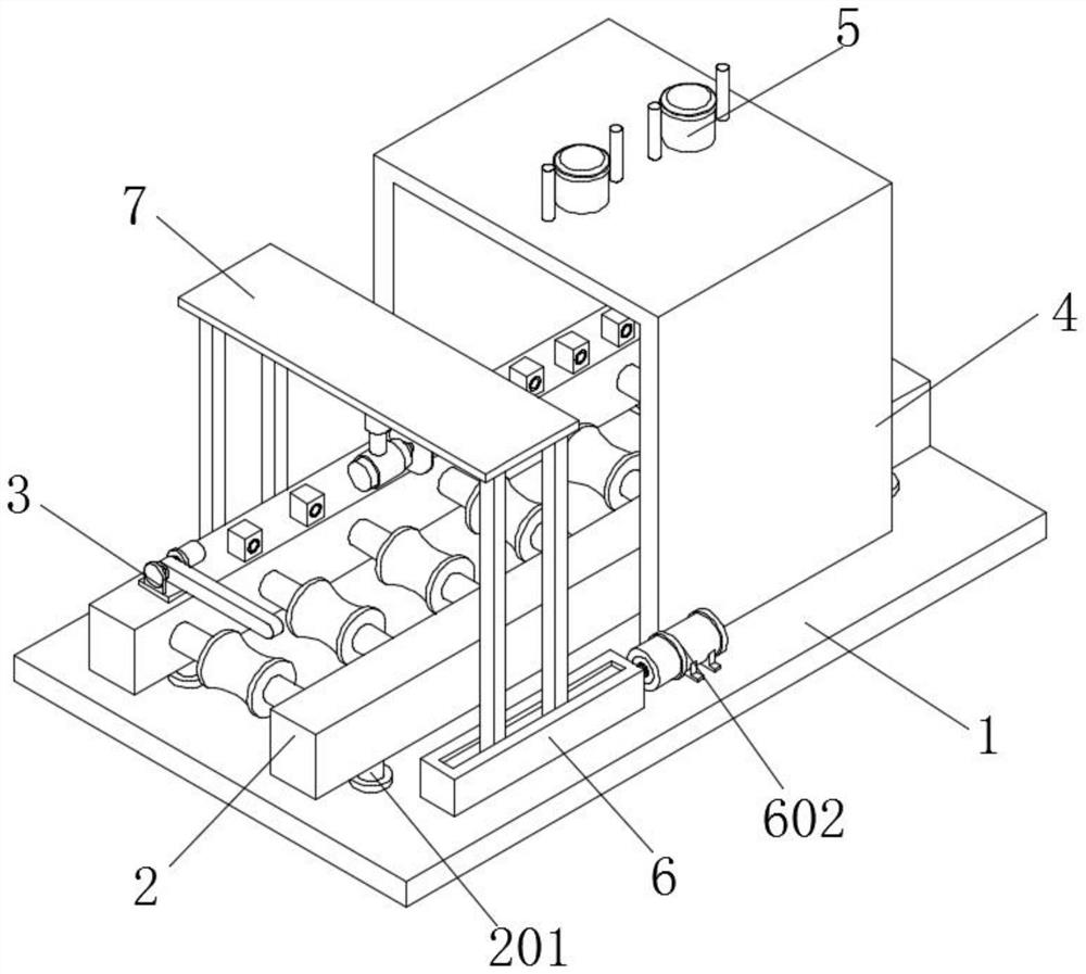
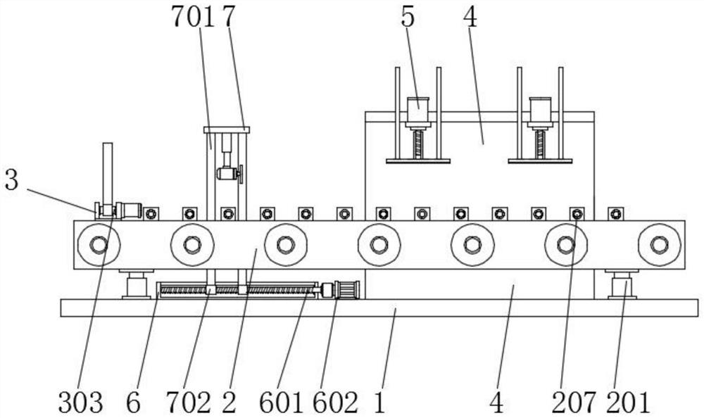
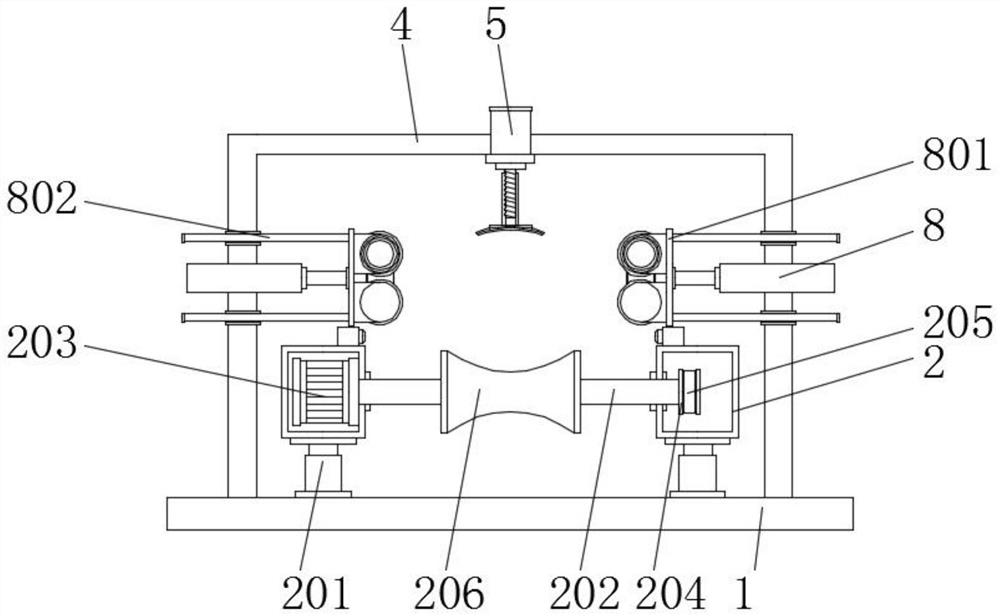
[0041] Embodiment 1 comprises a base plate 1, the top of the base plate 1 by a bolt mounted symmetrically arranged two lift pins 201, lift rod 201 supporting a pair of top floor, the lift rod 201 to ensure stability, the worker can adjust the lift rod according to length 201 controls the height of the support tube 2, to facilitate different thickness normal pipeline processing, the lifting rod 201 is attached to the top of the support tube 2, the lift lever 201 to the top of the support tube 2 is supported, to ensure that the support tube 2 stability, between the inner tube 2 through the two sets of support 202 is attached to a transmission rod, a set of inner support tube 2 is attached to the motor 203, the output of the motor 202 and drive rod 203 connected to active, the drive lever 202 away from the motor 203 One end of the first transmission wheel 204 is mounted, a first drive wheel 204 located on the other set of support of the inner tube 2, plural sets of first drive wheel ...

Embodiment 2

[0043] Embodiment 2 comprises a base plate 1, the top of the tube 2 is supported by a bolt mounting seat 3 is mounted, is mounted inside the movable seat 3 is mounted pawl 303, the side of the mounting seat 3 is attached to the servo motor 301, servo the output of the motor 301 and the rotation shaft 303 is connected to the pawl 303 outward is mounted movable rod 302, the support tube mounting base 2 pair of top 3 is fixed, easy to install turn base 3 medial 303 of the support, to complete the sanding pipe when the need for cutting by the movable rod 302 to block the pipe to prevent the pipe to move, after completion of the cutting, the servo motor 301 controls the rotation of the pawl 303, the pawl 303 to drive the active lever 302 outward tilt, so that the conduit may be normally transmitted out, after cutting out piped out, the servo motor 301 is running backward reverse rotation drive pawl 303 to drive the active lever 302 continues back to the original block of the pipeline; ...

Embodiment 3

[0045] Embodiment 3 comprises a base plate 1, the top of the base plate 1 by a bolt with a supporting frame 4, a pair of support plate supporting frame 4, to ensure stable support frame 4, and support frame 4 is located outside of the lift lever 201, the top support frame 4 is attached to a control motor through 5, conveniently supported by the support frame 4 is fixed to the control of the motor 5, the output of the control motor 5 there is mounted screw 501, the screw 502 threaded sleeve 501 is mounted outside , the bottom end of the inner threaded sleeve 502 is attached to the lifting plate 503, bottom plate 503 of the lifting plate 504 is attached to grinding, the top plate 503 is attached to the lift slider guide 505, the guide slider 505 positioned within the threaded sleeve 502 of the two side, the control operation of the motor 5 driven by the output of the screw 501 is rotated, the inner screw thread 501 of the inner sleeve 502 rotates drive screw is moved downward throug...


PUM


Abstract

The invention discloses an adjustable efficient cutting and grinding device for pipeline machining. The adjustable efficient cutting and grinding device for pipeline machining comprises a bottom plate, wherein two groups of symmetrically-arranged lifting rods are installed at the top of the bottom plate through bolts, supporting pipes are installed at the tops of the lifting rods, and installation seats are installed at the tops of the supporting pipes through bolts; and a supporting frame is installed at the top of the bottom plate through bolts and located at the outer sides of the lifting rods, a control motor is installed at the top of the supporting frame in a penetrating mode, and adjusting rods are installed on the outer walls of the two sides of the supporting frame in a penetrating mode. According to the invention, a screw rod is installed, an adjusting motor operates to drive the screw rod at an output end to rotate, the screw rod rotates to drive a lantern ring at the outer side to move through threads, and the lantern ring drives a supporting rod to move in the moving process, so that the position of a cutting device at the top is adjusted, and quantitative cutting for a pipeline by the device according to needs is facilitated.

Description

Technical field [0001] The present invention relates to the field of pipeline processing, and is specifically a highly cutting and grinding device for adjustable pipe processing. Background technique [0002] After the pipeline is produced, it is necessary to fine-grinding the outer surface of the pipeline, shielding the impurities of the pipe surface, increasing the finish and aesthetics of the surface of the pipe, and in the process of using the pipeline, it is necessary to segment the pipe Post-installation use. [0003] It is: [0004] 1. Comparative Document CN211464982U discloses a water conservancy engineering pipe cutting device, "including the bottom plate, the bottom of the bottom plate is fixedly coupled with a strut, the bottom of the strut, has a first base, the top of the bottom plate fixed connection The outer casing, the inner bottom wall of the outer casing fixedly connected to a table, and a slide groove is opened, and the inner wall of the slide groove is fixed...

Claims


Application Information

Patent Timeline
Patent Type & Authority Applications(China)
IPC IPC(8): B23P23/04B23Q7/00B23Q17/24
CPCB23P23/04B23Q17/24B23Q7/00
Inventor 赵建军仲睿赵建梅黄雷胡安龙严肖陈龚宏昌秦政徐俊峰夏仁杰杨海龙阮成浩
Owner NANTONG SHUGUANG ELECTROMECHINCAL ENG
Learn More