Electrolytic flotation tank combined drying foam layer circulation post-processing device

A post-processing device and electrolytic air flotation technology, which is applied in the directions of dry gas arrangement, flotation water/sewage treatment, grease/oily substance/suspton removal device, etc. The problem of narrow electrolysis area and other problems can achieve the effect of good after-treatment effect, low cost and enhanced utilization efficiency

Active Publication Date: 2021-12-07
YANCHENG INST OF TECH
View PDF4 Cites 0 Cited by
  • Summary
  • Abstract
  • Description
  • Claims
  • Application Information

AI Technical Summary

Problems solved by technology

[0004]However, when the existing electrolytic air flotation cell device is in operation, it generally only adopts the static electrolysis method, which makes the electrolysis area narrow and the electrolysis is insufficient, and the electrolysis cathode and the motor There is a certain distance from the bottom of the pool, and the generated air bubbles cannot effectively and quickly drive the suspended particles in the sewage to float up, resulting in a decrease in electrolysis efficiency. In addition, the air bubbles float up and form a layer of foam on the upper surface of the liquid, which cannot effectively treat the water in the foam layer. It has a certain impact on the recycling of waste residue

Method used


Image

  • Electrolytic flotation tank combined drying foam layer circulation post-processing device
  • Electrolytic flotation tank combined drying foam layer circulation post-processing device
  • Electrolytic flotation tank combined drying foam layer circulation post-processing device

Examples


Embodiment Construction

[0036] The preferred embodiments of the present invention will be described below in conjunction with the accompanying drawings. It should be understood that the preferred embodiments described here are only used to illustrate and explain the present invention, and are not intended to limit the present invention.

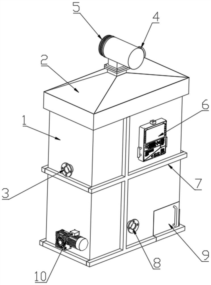
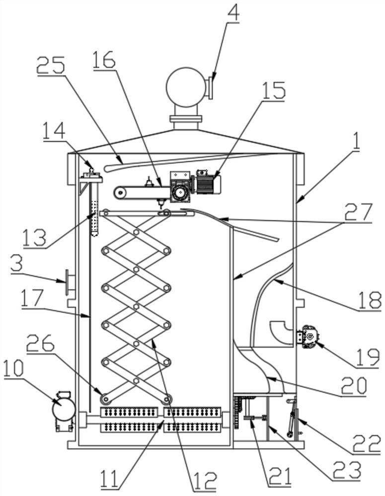
[0037] Such as figure 1 , 2 As shown, an electrolytic air flotation pool combined with a dry foam layer circulation post-processing device includes a frame mechanism, an electrolytic air flotation chamber, a drying chamber, a slag discharge box 9, and a control panel 6.

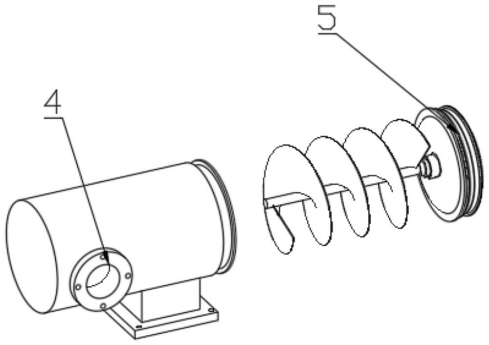
[0038] Such as figure 2 As shown, the frame mechanism includes a housing 1 and a top cover 2, the bottom of the housing 1 is provided with a base, and the top and the top cover 2 form a closed chamber, which is separated by a partition 27 into an electrolytic air flotation chamber, a drying The slag box 9 is connected under the drying chamber; the top cover 2 shrinks from bottom to top, a hot ga...


PUM


Abstract

The invention discloses an electrolytic flotation tank combined drying foam layer circulation post-processing device. The device comprises a frame mechanism, an electrolytic flotation chamber, a drying chamber, a slag discharging box and a control panel. The frame mechanism comprises a shell and a top cover, a water inlet is formed in the side face of the middle of the shell and used for receiving waste water, a water outlet is formed in the bottom of the shell and used for discharging purified water, and the water inlet and the water outlet are both communicated with the electrolytic flotation chamber. A stirring shaft, a telescopic unit, a slag scraping mechanism and a water quality detector are arranged in the electrolytic flotation chamber; stirring blades are mounted on the stirring shaft, the telescopic unit comprises a telescopic shear shank and a driver, and the electrodes periodically ascend and descend when the shear shank stretches out and draws back; and a scraping plate is used for scraping waste residue foam generated by electrolyzing wastewater to the drying chamber. Guide plates, electric heating blowers and sponges are arranged in the drying chamber. The problems of insufficient electrolytic flotation and drying of waste residue bubbles can be effectively solved, and waste residue recovery is facilitated.

Description

technical field [0001] The invention belongs to the technical field of sewage and waste water treatment, and in particular relates to a water treatment device for separating suspended matter in water and recovering waste residue. Background technique [0002] Sewage treatment refers to the process of purifying sewage to meet the water quality requirements for discharge into a certain water body or reuse. Sewage treatment is widely used in various fields such as construction, agriculture, transportation, energy, petrochemical, environmental protection, urban landscape, medical treatment, and catering. [0003] The air flotation process is a method commonly used in sewage treatment. Its principle is to pass direct current into the sewage, and a large number of tiny hydrogen bubbles with a diameter between 18 and 90 microns will be generated on the surface of the cathode in the sewage. The hydrogen bubbles and the small hydrogen bubbles in the wastewater Suspended particles ad...

Claims


Application Information

Patent Timeline
Patent Type & Authority Applications(China)
IPC IPC(8): C02F1/465C02F1/461C02F1/40F26B21/00
CPCC02F1/465C02F1/46104C02F1/46109C02F1/40F26B21/004C02F2201/002C02F2201/46105
Inventor 孟煜柏曹卫
Owner YANCHENG INST OF TECH
Why Eureka
Try Eureka