Optical lens, camera shooting module and electronic equipment

An optical lens and camera module technology, applied in optics, optical components, instruments, etc., can solve problems such as being unfavorable to the miniaturization and thinning of zoom optical lenses, difficult to meet the high-definition imaging requirements of optical lenses, and difficult to image clearly with optical lenses. , to achieve the effect of picture quality shooting experience, ingenious structure and reasonable number of lenses

Inactive Publication Date: 2021-12-07
NANCHANG OFILM HUAGUANG TECH CO LTD
View PDF6 Cites 0 Cited by
  • Summary
  • Abstract
  • Description
  • Claims
  • Application Information

AI Technical Summary

Problems solved by technology

In order to achieve clear imaging and achieve higher imaging quality, the number of lenses in the optical lens is also increasing. Among them, the number of lenses required by the zoom optical lens is more, resulting in an increasing volume of the zoom optical lens, which is not conducive to Development trend of miniaturization and thinning of zoom optical lens
That is to say, under the design trend of thin, light and miniaturized optical lenses, it is difficult for optical lenses to image clearly, with poor image quality and low resolution, and it is difficult to meet people's high-definition imaging requirements for optical lenses.

Method used


Image

  • Optical lens, camera shooting module and electronic equipment
  • Optical lens, camera shooting module and electronic equipment
  • Optical lens, camera shooting module and electronic equipment

Examples


no. 1 example

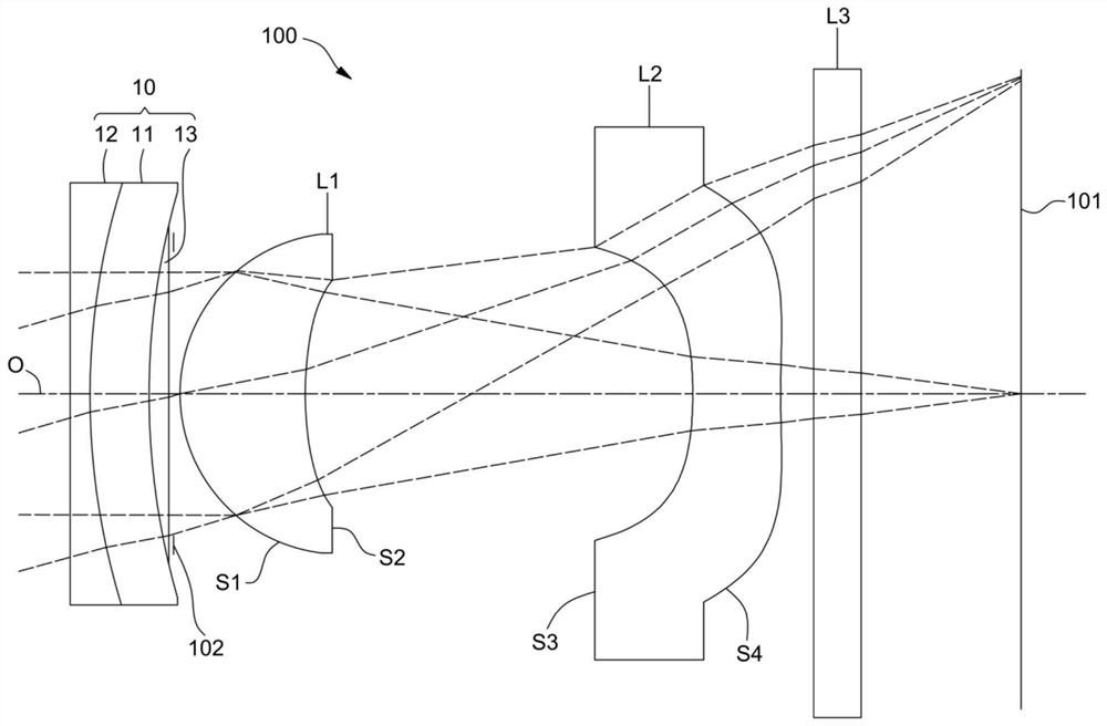
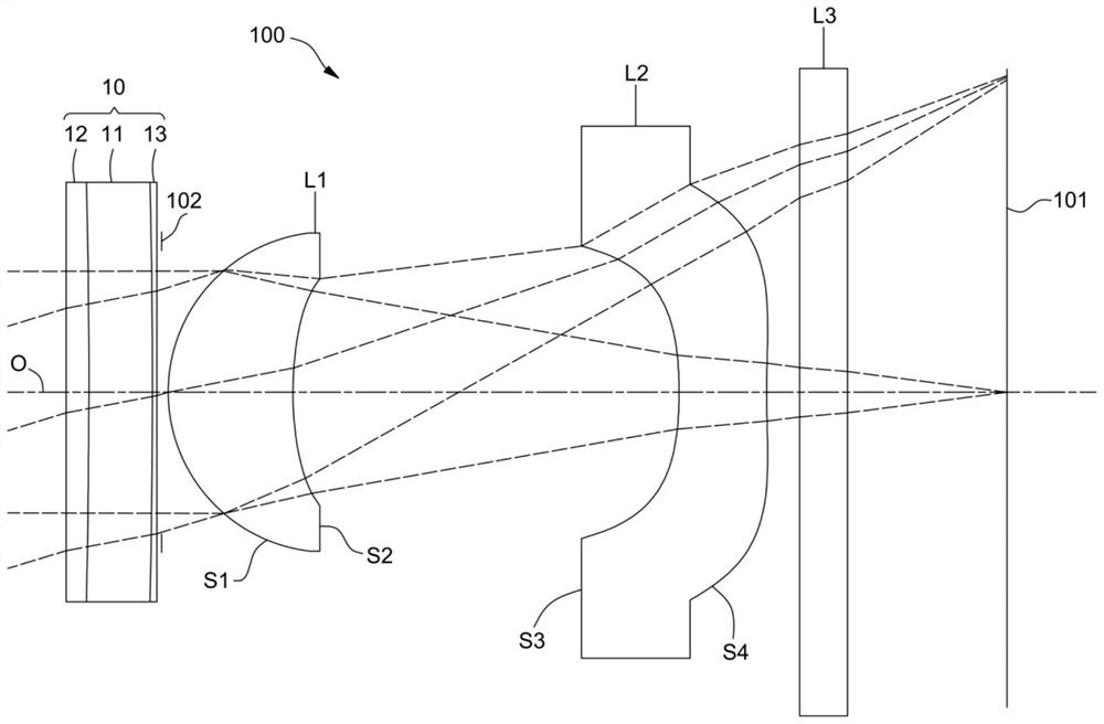
[0092] The structural diagram of the optical lens 100 disclosed in the first embodiment of the present application is as follows figure 1 , image 3 and Figure 5 As shown, the optical lens 100 includes a focusing assembly 10 , a diaphragm 102 , a first lens L1 , a second lens L2 and a filter L3 arranged in sequence along the optical axis O from the object side to the image side. Wherein, the material of the first lens L1 and the second lens L2 is plastic, the refractive power of the first lens L1 and the second lens L2 are both positive refractive powers, and the object side S1 and the image side S2 of the first lens L1 are on the optical axis O are respectively convex and concave, and both the object side S1 and the image side S2 of the first lens L1 are aspherical. The object side S3 and the image side S4 of the second lens L2 are respectively concave and convex at the optical axis O, and both the object side S3 and the image side S4 of the second lens L2 are aspherical. ...

no. 2 example

[0107] Please refer to Figure 7 , Figure 9 and Figure 11 , Figure 7 , Figure 9 and Figure 11 It is a schematic structural diagram of the optical lens 100 according to the second embodiment of the present application. The optical lens 100 includes a focusing assembly 10 , a diaphragm 102 , a first lens L1 , a second lens L2 and a filter L3 arranged in sequence along the optical axis O from the object side to the image side. Wherein, the material, refractive power and surface shape of the first lens L1 and the second lens L2 can be referred to the above-mentioned first embodiment, and will not be repeated here.

[0108] In the second embodiment, when the optical lens 100 is in the near-focus state, the middle-focus state or the far-focus state, the effective focal length f, the half field angle HFOV, the total optical length TTL, the aperture size FNO and other parameters of the optical lens 100 can be See Table 3 below. Wherein, definitions of other parameters in T...

no. 3 example

[0120] Please refer to Figure 13 , Figure 15 and Figure 17 , Figure 13 , Figure 15 and Figure 17 A schematic structural diagram of the optical lens 100 according to the third embodiment of the present application is shown. The optical lens 100 includes a focusing assembly 10 , a diaphragm 102 , a first lens L1 , a second lens L2 and a filter L3 arranged in sequence along the optical axis O from the object side to the image side. Wherein, the material, refractive power and surface shape of the first lens L1 and the second lens L2 can be referred to the above-mentioned first embodiment, and will not be repeated here.

[0121] In the third embodiment, when the optical lens 100 is in the near-focus state, the middle-focus state or the far-focus state, the effective focal length f, the half field angle HFOV, the total optical length TTL, the aperture size FNO and other parameters of the optical lens 100 can be See Table 5 below. Wherein, the definitions of other parame...


PUM


Abstract

The invention discloses an optical lens, a camera shooting module and electronic equipment. The optical lens comprises a focusing assembly, a first lens and a second lens which are sequentially arranged from an object side to an image side along an optical axis, wherein the focusing assembly comprises a focusing layer, the curvature radius of the focusing layer at the optical axis is a variable curvature radius, the first lens has positive refractive power, the second lens has positive refractive power, the optical lens meets the relational expression that the absolute value of Rly/Rlj is greater than 1 and less than 2.5, Rly is the curvature radius of the focusing layer at the optical axis in a far-focus state, and Rlj is the curvature radius of the focusing layer at the optical axis in a near-focus state. According to the optical lens, the camera shooting module and the electronic equipment provided by the invention, the curvature radius of the focusing assembly can be changed when objects with different object distances are shot while the light, thin and miniaturized design is met, so that incident light can be converged on the imaging surface of the optical lens, the optical lens is enabled to have high picture texture, resolution and imaging definition, and the high-definition imaging requirement of people on the optical lens is met.

Description

technical field [0001] The invention relates to the technical field of optical imaging, in particular to an optical lens, a camera module and electronic equipment. Background technique [0002] At present, with the wide application of electronic devices such as mobile phones, tablet computers, drones, and computers in daily life, people have higher and higher requirements for the imaging quality of optical lenses. achieve higher image quality. In order to achieve clear imaging and achieve higher imaging quality, the number of lenses in the optical lens is also increasing. Among them, the number of lenses required by the zoom optical lens is more, resulting in an increasing volume of the zoom optical lens, which is not conducive to The development trend of miniaturization and thinning of zoom optical lens. That is to say, under the design trend of thin, light and miniaturized optical lenses, it is difficult for optical lenses to image clearly, with poor image quality and lo...

Claims


Application Information

Patent Timeline
Patent Type & Authority Applications(China)
IPC IPC(8): G02B13/00G03B13/36G03B30/00
CPCG02B13/0015G02B13/009G03B13/36G03B30/00
Inventor 粘明德
Owner NANCHANG OFILM HUAGUANG TECH CO LTD
Why Eureka
Try Eureka