Connector with improved air tightness

A connector and air-tightness technology, applied in the direction of connection, two-part connection device, and parts of the connection device, can solve the problems of insufficient air-tightness, heat generation, moisture and moisture, etc., and extend the path of gas passage. , The effect of reducing the air gap area and improving the air tightness

Pending Publication Date: 2021-12-07
东莞市霍顿五金电子有限公司
View PDF1 Cites 0 Cited by
  • Summary
  • Abstract
  • Description
  • Claims
  • Application Information

AI Technical Summary

Problems solved by technology

[0002] Connectors usually include a terminal group and a terminal seat (also referred to as a plastic seat) that is injection-molded on the terminal group; the airtightness between the terminal group and the terminal seat of a traditional connector is not enough. In some areas with large temperature differences between day and night, when using It is easy to appear water mist on the corresponding security products, affecting its normal use
[0003] Taking the RJ45 socket connector as an example, in the prior art, you can refer to a circular RJ45 socket connector disclosed in Chinese patent ZL 202021287331.5, the fixed part of the terminal is connected to the terminal base through a flat smooth surface, When the connector is in use, it will generate heat, and the terminal base will produce a small amount of deformation, resulting in the formation of a certain gas circulation gap between the surface of the fixed part and the contact surface of the terminal base. In this connector, the gas circulation gap is smooth, so that the gas ( For example, humid air) can easily pass through the gas circulation gap from the front or rear of the terminal block, resulting in moisture inside the connector and inside the product, affecting the normal use of the product

Method used


Image

  • Connector with improved air tightness
  • Connector with improved air tightness
  • Connector with improved air tightness

Examples


Embodiment Construction

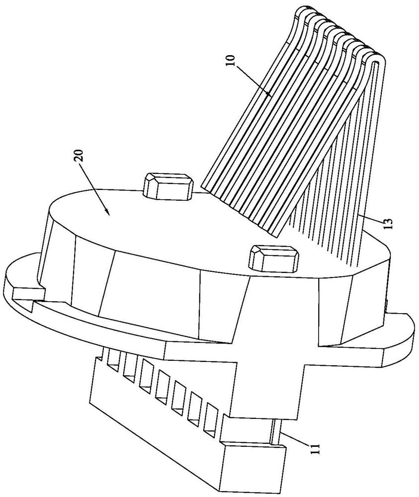
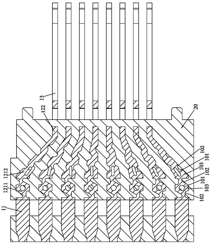
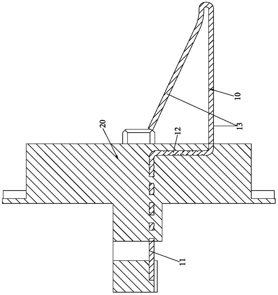
[0036] Please refer to Figure 1 to Figure 6 As shown, it shows the specific structure of the preferred embodiment of the present invention, including a terminal group 10 and a terminal seat 20 integrally injection molded outside the terminal group 10, each terminal in the terminal group 10 includes The solder leg part 11, the fixed part 12, and the contact part 13 are connected in sequence. The solder leg part 11 protrudes backward from the terminal base 20, the fixed part 12 is buried in the terminal base 20, and the contact part 13 is forward extending out of the terminal block 20;

[0037] The fixing part 12 is provided with a through hole 101 penetrating through the upper surface and the lower surface of the fixing part 12, and the left side and the right side of the fixing part 12 are provided with a plurality of recesses arranged at intervals along the extending direction of the fixing part 12. 102, a protrusion 103 is formed between adjacent concave positions 102; the...


PUM


Abstract

The invention discloses a connector with improved air tightness. The connector comprises a terminal set and a terminal seat which is integrally formed outside the terminal set in an injection molding mode, each terminal in the terminal set comprises a welding foot part, a fixing part and a contact part which are sequentially connected, the welding foot part backwards extends out of the terminal seat, the fixing part is embedded in the terminal seat, the contact part forwards extends out of the terminal seat, a through hole penetrating through the upper surface and the lower surface of the fixing part is formed in the fixing part, a plurality of concave positions arranged at intervals in the extending direction of the fixing part are arranged on the left side face and the right side face of the fixing part, and protrusions are formed between the adjacent concave positions. And the terminal seat is injected into the through hole and the concave position, so that the left side surface and the right side surface of the fixing part are combined with the terminal seat through corrugated curved surfaces which are alternately arranged in a concave-convex manner. The area of the side surface of the terminal is increased, the terminal and the terminal seat are combined more tightly, the air gap area through which gas can pass is reduced, the gas passing path is prolonged, and the air tightness of the connector is improved.

Description

technical field [0001] The invention relates to the technology in the field of connectors, in particular to a connector with improved airtightness, which mainly refers to an RJ connector. Background technique [0002] The connector usually includes a terminal group and a terminal seat (also referred to as a plastic seat) injection-molded on the terminal group; the airtightness between the terminal group and the terminal seat of the traditional connector is not enough, and in some areas with large temperature differences between day and night, when using It is easy to have water mist on the corresponding security products, affecting its normal use. [0003] Take the RJ45 socket connector as an example. In the prior art, you can refer to a circular RJ45 socket connector disclosed in Chinese patent ZL 202021287331.5. The fixed part of the terminal is connected to the terminal base through a flat smooth surface. When the connector is in use, it will generate heat, and the termi...

Claims


Application Information

Patent Timeline
Patent Type & Authority Applications(China)
IPC IPC(8): H01R13/52H01R13/405H01R13/02H01R13/04H01R24/64
CPCH01R13/521H01R13/405H01R13/02H01R13/04H01R24/64
Inventor 李波
Owner 东莞市霍顿五金电子有限公司
Why Eureka
Try Eureka