Electronic equipment and control method

A technology for electronic equipment and equipment, applied in the computer field, can solve the problems of increasing the cost of computer configuration, and the functions cannot be better applied, and achieve the effect of reducing the configuration cost and the occupation of processing resources.

Pending Publication Date: 2021-12-07
LENOVO (BEIJING) CO LTD
0 Cites 0 Cited by

AI-Extracted Technical Summary

Problems solved by technology

[0003] However, in order to realize this specific remote transmission function, a professional network card supporting this functi...

Method used

...

Abstract

The invention discloses electronic equipment and a control method. The electronic equipment comprises a control chip and a network card chip connected with the control chip, and a remote management engine is arranged in the network card chip; the wireless fidelity WIFI module is connected with the network card chip, and the wireless fidelity WIFI module can be in signal connection with a remote management engine so as to receive the control of the first management end equipment through the remote management engine under the condition that the first network connection with the first management end equipment is established. A special chip satisfying remote management does not need to be configured in a wireless fidelity WIFI module, remote management control can be received through the network card chip, and configuration cost and occupation of processing resources are reduced.

Application Domain

Assess restrictionConnection management +1

Technology Topic

Embedded systemComputer hardware +3

Image

  • Electronic equipment and control method
  • Electronic equipment and control method
  • Electronic equipment and control method

Examples

  • Experimental program(1)

Example Embodiment

[0030] The technical solutions in the embodiments of the present application will be clearly and completely described below with reference to the drawings in the embodiments of the present application. Obviously, the described embodiments are only a part of the embodiments of the present application, but not all of the embodiments. Based on the embodiments in the present application, all other embodiments obtained by those of ordinary skill in the art without creative efforts shall fall within the protection scope of the present application.
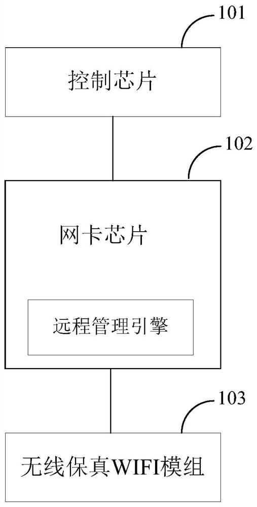
[0031] The embodiment of the present application provides an electronic device, which can be remotely connected with other electronic devices and can respond to remote control information. see figure 1 , a schematic structural diagram of an electronic device provided in Embodiment 1 of the present application, the electronic device may at least include:
[0032] Control chip 101 , network card chip 102 and Wi-Fi module 103 .
[0033] The network card chip 102 is connected to the control chip 101 , and a remote management engine is set in the network card chip 102 . The Wi-Fi WIFI module 103 is connected to the network card chip 102 and can be signal-connected to the remote management engine, so as to receive the control of the first management device through the remote management engine when the first management device establishes the first network connection.
[0034] The control chip 101 is a part of the main board of the electronic equipment, and has a core role in the control of the electronic equipment, and is used to control and coordinate the operation of each component in the electronic equipment system, such as controlling the opening, closing, connection, disconnection of the hardware part, etc. The control software part can control the reception, output and processing of data, and can also control the response or complete the connection or data interaction with other electronic devices, such as controlling the response of the electronic device to the remote management signal of the electronic device connected to it remotely.
[0035] Correspondingly, in the embodiment of the present application, the control chip includes any one of the following: a central processing unit, a south bridge chip, or a system-on-chip. Among them, the central processing unit (CPU), as the operation and control core of the computer system, is the final execution unit of information processing and program operation, which can realize the processing of the relevant data received or generated by the electronic equipment, such as generating and The display interface that matches the received data, for example, responds to the obtained remote management signal, and generates response information.
[0036] The south bridge chip is one of the chips based on the computer motherboard chipset architecture. The south bridge chip is responsible for the communication between I/O buses, such as PCI bus, USB, LAN, ATA, SATA, audio controller, keyboard controller, Real-time clock controller, advanced power management, etc. There are different types of south bridge chips. The commonly used types of south bridge chips are PCH (PlatformController Hub, integrated south bridge). For example, the South Bridge chip responds to the transmitted network signal.
[0037] System on Chip (SOC) refers to a chip that integrates different control chips, which can be a system-level chip control logic module, a microprocessor/microcontroller CPU core module, a digital signal processor DSP module, embedded memory module, interface module for external communication, analog front-end module with ADC/DAC, power supply and power management module, for a wireless SOC there is also RF front-end module, user-defined logic (which can be implemented by FPGA or ASIC) ) and micro-electromechanical modules, more importantly, a SOC chip is embedded with basic software (RDOS or COS and other application software) modules or loadable user software.
[0038] The network card chip 102 is an integrated chip that integrates network functions, and realizes the reception, processing and management of network signals. Specifically, the network card chip may be a LAN IC (Local Area Network Integrated Circuit, local area network integrated circuit). It should be noted that in the embodiment of the present application, the network card chip is provided with a remote management engine (Dashengine), and the remote management engine may be able to realize Dash function, Dash (Desktop and mobileArchitecture for System Hardware) provides open standards-based Web service management for desktop and mobile client systems, Dash allows real-time secure and reliable out-of-band management, enabling remote management, boot control, secure transmission, Operating system status acquisition and other related functions, among which, remote management can include remote power control, boot control and console redirection, remote diagnosis, remote system status monitoring, etc. The remote management control signal from the management end device is received through the remote management engine in the network card chip.
[0039]The wireless fidelity WIFI module 103 is connected with the network card chip, and can be connected with the signal of the remote management engine, that is, the wireless guarantee WIFI module can transmit the signal meeting the processing conditions of the remote management engine to the remote management engine to communicate with the first management engine. When the end device establishes the first network connection, it receives the control of the first management end device through the remote management engine. Wherein, the first management terminal device refers to a device that can perform data interaction with the electronic device, and can manage or control the electronic device. For example, remote management control of the electronic device can be achieved. It should be noted that there may be at least one management terminal device corresponding to the electronic device, and different control modes may be executed on the electronic device based on different management terminal devices. Since the wireless fidelity WIFI module realizes the transmission of wireless network signals, the first network is a wireless network.
[0040] The first management terminal device transmits the control signal to the wireless fidelity WIFI module in the wireless network transmission mode, and the wireless fidelity WIFI module transmits the control signal to the remote management engine of the network card chip, so that the remote management engine receives the As for the control signal, the control signal can then be sent to the control chip so that the control chip responds to the control signal. Correspondingly, the remote management engine may also accept the control of the first management terminal device to achieve a target state, such as controlling the working state (on or off) of the remote management engine.
[0041] In the embodiment of this application, an ordinary wireless fidelity WIFI module can be used to receive the specific control signal of the management device, and the Dash function can be realized through the remote management engine set in the network card chip, without using a specific wireless fidelity device that supports the Dash function. The WIFI module saves the configuration cost of the wireless fidelity WIFI module, and can directly transmit the signal received by the wireless fidelity WIFI module to the network card chip, saving the transmission resources of the system.
[0042] In a possible implementation manner, the network card chip is connected to the control chip through the first communication interface, and the wireless fidelity WIFI module is connected to the network card chip through the second communication interface, wherein the communication capability of the first communication interface is stronger than that of the second communication interface. The communication capability of the communication interface.
[0043] Among them, the first communication interface can complete the data transmission between the network card chip and the control chip, mainly including converting the data format transmitted by the network card chip into a data format that can be recognized by the control chip. The data format is converted into a data format that can be recognized by the network card chip. Moreover, the first communication interface also has the function of controlling the signal, for example, identifying the signal transmitted by the network card chip to determine whether to transmit the signal to the corresponding control chip, or to which control chip the signal is transmitted to. specific modules. For example, after the remote management engine in the network card chip receives the control signal transmitted by the first management terminal device through the wireless fidelity WIFI module, the network card chip can transmit the control signal to the control chip through the first communication interface, and the control chip can Including the first control module and the second control module, by default, the control signal is sent to the first control module, but if the first control module is currently in an occupied state, for example, when processing other signals, the first communication interface can control the The control signal is transmitted to the second control module to ensure a response to the control signal.
[0044] Correspondingly, the wireless fidelity WIFI module communicates with the network card chip through the second communication interface. Wherein, the second communication interface can transmit the signal of the wireless fidelity WIFI module and the network card chip, and the second communication module can have the function of data format conversion and transmission, such as the signal format of the wireless network signal can be converted into the network card chip. The recognized signal format can also convert the signal format of the network card chip into the format of the wireless network signal, which is convenient for signal transmission. Specifically, the second communication interface may be PCle Gen1, which is a communication interface of a high-speed serial computer expansion bus with a maximum transmission rate of 2.5Gb/s.
[0045] Since the first communication interface is connected to the control chip, and the control chip is the main function chip of the electronic device, in addition to receiving the data transmitted by the network card chip, it can also receive the data transmitted by other chips, such as audio, video and other processing chips. Therefore, , the first communication interface not only undertakes the task of transmitting the data of the network card chip, but also needs to transmit the tasks of other processing chips. In order to ensure the normal transmission of data, it is necessary to make the communication capability of the first communication interface stronger than that of the second communication interface. For example, when the second communication interface is PCle Gen1, the first communication interface can be PCleGen2, and the maximum transmission rate of PCle Gen2 can reach 5.0Gb/s. Correspondingly, the communication capability may be reflected in the transmission rate or the number of transmission channels, for example, the parallel data transmission channels corresponding to the first communication interface may be more than the parallel data transmission channels corresponding to the second communication interface. When the second communication interface is PCle Gen1, the wireless fidelity WIFI module may include a connector, so that the pins of PCle Gen1 are connected to the connector. Correspondingly, when the second communication interface is another type of interface, the wireless fidelity WIFI module may have a connector adapted to the second communication interface, so as to realize signal connection with the second communication interface.
[0046] Among them, the first communication interface can control the control signal from the first management device input by the remote management engine to the control chip, so as to be able to decide whether to send the control signal to the corresponding component to perform the corresponding operation, and the control signal is received by the wireless fidelity WIFI module And send it to the remote management engine through the second communication interface.
[0047] The control signal of the first management device may have different control methods or different control purposes. Therefore, the first communication interface can identify the control signal to determine whether the control signal is input to the control chip for execution, or specifically to the The components corresponding to the control chip perform corresponding operations. For example, the current electronic device is in the shutdown state, and the control signal is to control the electronic device to be turned on. If the control chip can only process data when the electronic device is turned on, the first communication interface will transmit the signal to control the electronic device to be turned on. The power-on guidance processing component is used to realize the remote power-on control of the electronic device. In another way, if the control chip includes different response components, it can be determined to send the control signal to the target component for execution by combining the specific information of the management device that the control signal is sent from, such as which management device it comes from, and analyzing the signal. The corresponding operation, for example, the control signal is to control the audio output transmitted by the management device, then the audio component may be controlled to output the transmitted audio through the first communication interface.
[0048] In an implementation manner of the embodiment of the present application, the network card chip may also include a wired network interface in addition to a wireless fidelity WIFI module, so as to establish a second network connection with the second management terminal device through the wired network interface, so as to transfer data from The control signal of the second management terminal device is input to the control chip through the remote management engine.
[0049] Since the network card chip includes a wired network interface, the second network connection is a wired network connection. In the embodiment of the present application, the wired network control signal from the management terminal device can be received, and the control signal can be a control signal to realize the Dash function, and the transmission of the signal can be realized by sending the signal to the remote management engine of the network card chip, In order to complete the control of the electronic device by the management terminal device. Therefore, in this embodiment, the wired network interface does not need to be configured with a specific module supporting the Dash function, and only needs to use the remote management engine of the network card chip to realize the support for the Dash function.
[0050] It should be noted that, in this implementation manner, the second management terminal device may be the same device as the first management terminal device, or may be different devices. If it is the same device, the management device can be connected to the electronic device with a wired network or a wireless network connection, which can be based on the network environment where the management device and the electronic device are located, network parameters, and the specific type of corresponding transmission data , choose to establish the signal transmission with the electronic device through the wireless fidelity WIFI module or through the wired network interface. If they are different devices, connect to the second management device through a wired network interface, and connect to the first management device through a wireless fidelity WIFI module. The remote management engine can transmit the control signals according to the order of signal transmission, or can transmit the control signals according to the priority of signal transmission. For example, the priority of the second management device connected to the wired network interface is higher than that of the first management device connected to the wireless fidelity WIFI module. The control signal of the management terminal device.
[0051] In one embodiment, the remote management engine can simultaneously send control signals from the first management device and the second management device to the control chip, so that the electronic device responds to the signals from the first management device and the second management device at the same time. control signal.
[0052] When the electronic device responds to the control signals from the first management device and the second management device at the same time, it may be that the same hardware of the electronic device responds to the control signals from the first management device and the second management device. For example, the control signal generated by the first management device is a signal for querying the status of the fan, and the control signal generated by the second management device is a signal for querying the power state, then when the remote management engine sends the control signal to the control chip of the electronic device, the control The chip will make the corresponding fan status information generate a corresponding fan status interface, and the power status corresponds to the power status interface, and the control chip will control the display device of the electronic device to respond to the control signals of the first management device and the second management device at the same time, Outputting the fan status interface and the power status interface on the display device may also be to make the image transmission device of the electronic equipment respond to the control signal, so that the image transmission device outputs the fan status interface and the power status interface to the first management device and the second management device respectively. Manage devices.
[0053] In another implementation manner, the same software of the electronic device may also respond to the control signals from the first management device and the second management device at the same time. For example, the control signal generated by the first management device is a control signal for remotely diagnosing the disk, and the control signal generated by the second management device is a control signal for remotely diagnosing the boot system of the electronic device, then when the remote management engine sends the control signal to the electronic device After controlling the chip, the control chip will start the diagnosis application of the electronic device to respond to the above control signal, and realize the diagnosis of the disk and the diagnosis of the boot system.
[0054] In yet another implementation manner, the hardware and software of the electronic device may also respond to control signals from the first management device and the second management device at the same time. For example, if the control signal generated by the first management device is to remotely control the update of the desktop wallpaper of the electronic device, the first management device will send the corresponding target image as the desktop wallpaper of the electronic device. When the remote management engine receives the control signal and When the target image is selected, the control signal and the target image will be transmitted to the control chip, and the control chip will control the desktop output part of the electronic device to output the target image as the current desktop. If the control signal of the state of the hardware configuration in the remote monitoring system generated by the second management device is received at the same time, when the control chip obtains the control signal through the remote management engine, it will control the state monitoring application to start to obtain the hardware configuration state, and transmit the obtained state signal to the second management device through the transmission component.
[0055] see figure 2 Another structural schematic diagram of an electronic device provided in the embodiment of the present application, in figure 2 In the corresponding embodiment, the control chip is CPU, the network card chip is LAN IC, the first communication interface is Pcle Gen2, the second communication interface is Pcle Gen1, the remote management engine is Dash engine, and the wired network interface can be LAN RJ45, corresponding Yes, the wired network interface and the Dash engine can be connected through a communication module. The communication module can be composed of a transmitter receiver (Transceiver) and a MAC controller. The communication module can convert the analog signal format corresponding to the wired network signal into a digital signal format, and then transmit the converted digital signal to the Dash engine.
[0056]Specifically, the wireless fidelity WIFI module transmits the wireless control signal from the management device to Pcle Gen1, and after the data format conversion is completed by Pcle Gen1, the wireless control signal is transmitted to the Dash engine, and then transmitted by Dasheng engine to Pcle Gen2 , Pcle Gen2 completes the conversion of the relevant data format and transmits it to the CPU, so that the CPU responds to the wireless control signal. Correspondingly, the wired control signal from the management device can also be transmitted to the transmitting receiver through LAN RJ45, and then sent to the MAC controller, and then the MAC controller sends the wired control signal after data format conversion to the Dash engine, Then it is transmitted to Pcle Gen2 by the Dash engine, and the relevant data format is converted by Pcle Gen2 and then transmitted to the CPU, so that the CPU can respond to the wired control signal.
[0057] It should be noted that the first communication interface, the second communication interface and the communication module can all be part of the network card chip (such as figure 2 As shown), it can also be used as an external component of the network card chip, connected through the corresponding connection structure of the network card chip.
[0058] exist figure 2 In the illustrated embodiment, by utilizing the remote management engine (Dashengine) of the current network card chip (LAN IC), the received control signal of the wireless fidelity WIFI module is connected to the LAN IC, and a group is shared by the LAN IC and WIFI. Dash engine, so that the ordinary WIFI module without Dash engine can also realize the WIFI dash function, and can save Pcle resources on the CPU side.
[0059] Based on the foregoing electronic equipment, an embodiment of the present application also provides a control method applied to the electronic equipment, see image 3 , the method may include the following steps:
[0060] S201. Detect whether the electronic device establishes a first network connection with the management device through its wireless fidelity WIFI module, and if so, execute S202.
[0061] S202. Forward the control signal from the management device to the control chip of the electronic device through the remote management engine of the network card chip.
[0062] S203. Control corresponding components of the electronic device to perform corresponding operations through the control chip.
[0063] The wireless fidelity WIFI module of the electronic device sends a specific wireless network signal to the management terminal device. If the management terminal device can receive the specific wireless network signal, it can indicate that the electronic device communicates with the management terminal through the wireless fidelity WIFI module. The device has established a wireless network connection. Since the remote management engine of the network card chip can identify and transmit the control signal from the management device, the remote management engine forwards the control signal to the control chip. According to different functions corresponding to the control signals, the control chip can control the corresponding components of the electronic device to respond to or perform operations corresponding to the control signals. For example, if the control signal is to control the power of the electronic device to be turned on, the control chip will control the power-on component of the electronic device to be turned on, and furthermore, the operating system of the electronic device can be started.
[0064] Correspondingly, in a possible implementation manner, the control method further includes:
[0065] During the power-on self-test process of the electronic device, at least the configuration information of the network card chip is obtained, so as to control the remote management function of the electronic device based on the wireless fidelity WIFI module to be in an enabled or disabled state at least based on the configuration information.
[0066] Wherein, the power-on self-check process of the electronic device may be a check process of a BIOS (Basic Input Output System, Basic Input Output System) of the electronic device. The configuration information of the network card chip may include function configuration information of the network card chip, information of external components of the network card chip, or status information of the network card chip. Wherein, the function configuration information of the network card chip may include whether the network card chip can work normally, or whether a remote management engine is configured in the network card chip, or whether the remote management engine is in a normal working state. The external component information of the network card chip may include whether the network card chip is mounted with a wireless fidelity WIFI module, or whether the network card chip has a corresponding wired network interface.
[0067] Then, at least based on the configuration information, the wireless fidelity WIFI module-based remote management function of the electronic device is controlled to be in an enabled or disabled state. For example, if the wireless fidelity WIFI module is not mounted on the network card chip through the configuration information, then the remote management function of the electronic device based on the wireless fidelity WIFI module is controlled to be in a disabled state. For another example, if the network card chip is configured with a remote management engine and mounted with a wireless fidelity WIFI module through the configuration information of the network card chip, then the remote management function of the electronic device based on the wireless fidelity WIFI module is controlled to be in an enabled state , that is, it can receive the control signal from the control device.
[0068] In another embodiment of the present application, according to different states of the electronic device, it is also possible to control in which network mode the electronic device receives the control signal of the management terminal device. Correspondingly, the control method may also include:
[0069] In a possible implementation, if the electronic device is in the first running state, use the wired network interface of the electronic device to establish a second network connection with the management end device, so as to transmit the control signal from the management end device to the Control chip input.
[0070] The first operating state of the electronic device may be determined based on the power consumption state of the electronic device. For example, when the electronic device is in a low power consumption state, the current state of the electronic device is determined as the first operating state. When the electronic device is in a state of low power consumption, the wireless fidelity WIFI module of the electronic device may not work normally due to the power-off processing to reduce energy consumption. At this time, the wired network interface of the electronic device will establish a second Internet connection (wired Internet connection). Specifically, the low power consumption state may be a power-off state, a standby state or a sleep state of the electronic device.
[0071] In another possible implementation manner, if the electronic device enters the second operating state from the first operating state, the first network connection is used to receive the control signal from the management terminal device. The low power consumption state corresponding to the first operation state, the second operation state is a high power consumption state relative to the first operation state, for example, the second operation state is a normal operation state, if the first operation state is a standby state, when When the electronic device switches from the standby state to the normal working state, it can receive a control signal from the management terminal device through the first network connection (wireless network connection).
[0072] In yet another possible implementation manner, if the electronic device is in the second running state, use the first network connection and the second network connection to receive the control signal from the management terminal device. The second operating state can be the normal working state of the electronic device. At this time, the wireless fidelity WIFI module and the wired network interface of the electronic device can both work normally. Therefore, the first network connection and the second network connection can be used to receive information from the management The control signal of the end device. At this time, it may be determined based on the network status of the management terminal device or the electronic device whether to connect via the first network connection or the second network connection. For example, when the wireless network signal of the management terminal device is in an unstable state, the control signal of the management terminal device may be received through a wired network connection. For example, when it is detected that the distance between the management terminal device and the electronic device is greater than the distance threshold, in order to realize convenient transmission, the connection may be made through the first network connection (ie, wireless network connection).
[0073] Further, it may also be determined according to the type and/or attribute of the control signal whether to receive the control signal from the management device through the first network connection or to receive the control signal from the management device through the second network connection. Specifically, according to the type of the control signal, such as whether the control signal includes a synchronously transmitted file or a simple control command, if it only includes a control command, any network connection method can be used for connection. If the control signal also includes related files, such as text files, images, or audio and video, etc., it is necessary to rely on stable network transmission to ensure the normal transmission of files. Therefore, the second network connection (wired network connection) may be preferentially selected. On the other hand, the size of the transmitted data volume can also be determined based on the attributes of the control signal, and the target network connection mode can be determined based on the current network environment and the size of the data volume. If the amount of data is large, in order to prevent data loss caused by network lag, you can use a wired network connection to receive the data. On the contrary, the data can be received by means of wireless network connection.
[0074] In an implementation manner of the embodiment of the present application, the control method further includes:
[0075] If the control signal for controlling the electronic device to start is obtained from the management terminal device, perform a start-up operation.
[0076] Wherein, the control signal for controlling the power-on of the electronic device may be a direct power-on signal, that is, the electronic device is currently in a shutdown state, and the management terminal device may generate a remote power-on signal so that the power-on signal is connected through a wired network. transmit to the remote management engine, and make the remote principle engine forward the start-up signal to the control chip, and the control chip controls the start-up of the boot program and completes the start-up operation.
[0077] Correspondingly, the management device can also directly send the corresponding remote management control signal to the electronic device. When the electronic device is currently in the shutdown state, it first controls the electronic device to start, and then controls the control chip to execute the remote management after the electronic device is started. The control signal matches the control operation.
[0078] In a control method provided in the embodiment of this application, if the electronic device establishes a first network connection with the management device through its wireless fidelity WIFI module, the remote management engine of the network card chip will send the control signal from the management device to The information is forwarded to the control chip of the electronic device, so that the control chip controls corresponding components of the electronic device to perform corresponding operations. It is realized that there is no need to configure a dedicated chip for remote management in the wireless fidelity WIFI module, and the remote management control can be received through the network card chip, which reduces the configuration cost and the occupation of processing resources.
[0079] In the embodiment of the present application, a control device is also provided, see Figure 4 , the control unit consists of:
[0080] The signal forwarding unit 301 is used to forward the control signal from the management terminal device to the electronic device through the remote management engine of the network card chip if the electronic device establishes a first network connection with the management terminal device through its wireless fidelity WIFI module. control chip
[0081] The control unit 302 is configured to control corresponding components of the electronic device to perform corresponding operations through the control chip.
[0082] Further, the control device also includes:
[0083] An information acquisition unit, configured to obtain at least the configuration information of the network card chip during the power-on self-inspection process of the electronic device, so as to control the remote management function of the electronic device based on the wireless fidelity WIFI module at least based on the configuration information. enabled or disabled state.
[0084] Optionally, the control device also includes:
[0085] a signal input unit, configured to use the wired network interface of the electronic device to establish a second network connection with the management device if the electronic device is in the first operating state, so as to pass the control signal from the management device through the a remote management engine inputs to said control chip; or,
[0086] A first signal receiving unit, configured to use the first network connection to receive a control signal from the management terminal device if the electronic device enters a second operating state from the first operating state; or,
[0087]A second signal receiving unit, configured to receive a control signal from the management end device by using the first network connection and the second network connection if the electronic device is in a second operating state.
[0088] Further, the control device also includes:
[0089] The power-on execution unit is configured to execute a power-on operation if a control signal for controlling the power-on of the electronic device is obtained from the management terminal device.
[0090] In the control device provided by the embodiment of the present application, if the electronic device establishes a first network connection with the management end device through its wireless fidelity WIFI module, the control signal from the management end device is transmitted through the remote management engine of the network card chip. It is forwarded to the control chip of the electronic device, so that the control chip controls the corresponding components of the electronic device to perform corresponding operations. It realizes that there is no need to configure a dedicated chip for remote management in the wireless fidelity WIFI module, and the remote management control can be received through the network card chip, which reduces the configuration cost and the occupation of processing resources.
[0091] It should be noted that, for the specific implementation of the control device in this embodiment, reference may be made to the corresponding content in the foregoing, which will not be described in detail here.
[0092] The various embodiments in this specification are described in a progressive manner, and each embodiment focuses on the differences from other embodiments, and the same and similar parts between the various embodiments can be referred to each other. As for the device disclosed in the embodiment, since it corresponds to the method disclosed in the embodiment, the description is relatively simple, and the relevant part can be referred to the description of the method.
[0093] Professionals may further realize that the units and algorithm steps of each example described in conjunction with the embodiments disclosed herein can be implemented in electronic hardware, computer software, or a combination of the two, in order to clearly illustrate the possibilities of hardware and software. Interchangeability, the above description has generally described the components and steps of each example in terms of functionality. Whether these functions are performed in hardware or software depends on the specific application and design constraints of the technical solution. Skilled artisans may implement the described functionality using different methods for each particular application, but such implementations should not be considered beyond the scope of this application.
[0094] The steps of a method or algorithm described in conjunction with the embodiments disclosed herein may be directly implemented in hardware, a software module executed by a processor, or a combination of the two. A software module can be placed in random access memory (RAM), internal memory, read only memory (ROM), electrically programmable ROM, electrically erasable programmable ROM, registers, hard disk, removable disk, CD-ROM, or any other in the technical field. in any other known form of storage medium.
[0095] The above description of the disclosed embodiments enables any person skilled in the art to make or use the present application. Various modifications to these embodiments will be readily apparent to those skilled in the art, and the generic principles defined herein may be implemented in other embodiments without departing from the spirit or scope of the present application. Therefore, this application is not intended to be limited to the embodiments shown herein, but is to be accorded the widest scope consistent with the principles and novel features disclosed herein.

PUM

no PUM

Description & Claims & Application Information

We can also present the details of the Description, Claims and Application information to help users get a comprehensive understanding of the technical details of the patent, such as background art, summary of invention, brief description of drawings, description of embodiments, and other original content. On the other hand, users can also determine the specific scope of protection of the technology through the list of claims; as well as understand the changes in the life cycle of the technology with the presentation of the patent timeline. Login to view more.
Why Eureka
Try Eureka