Ocean engineering crane test bench

A technology of marine engineering and cranes, which is applied in the field of test benches, can solve the problems that the height of the test bench cannot be adjusted, the operating space is limited, and the simulation progress is affected, and the effect of simple adjustment, simple height, and improved use efficiency can be achieved.

Inactive Publication Date: 2021-12-10
彭宏宽
View PDF4 Cites 0 Cited by
  • Summary
  • Abstract
  • Description
  • Claims
  • Application Information

AI Technical Summary

Problems solved by technology

[0004] The purpose of the present invention is to solve the shortcomings that the existing test bench cannot be adjusted simply, and the operating space is limited, which greatly reduces its use efficiency and affects the simulation progress, and proposes a test bench for marine engineering cranes

Method used


Image

  • Ocean engineering crane test bench
  • Ocean engineering crane test bench
  • Ocean engineering crane test bench

Examples


Embodiment 1

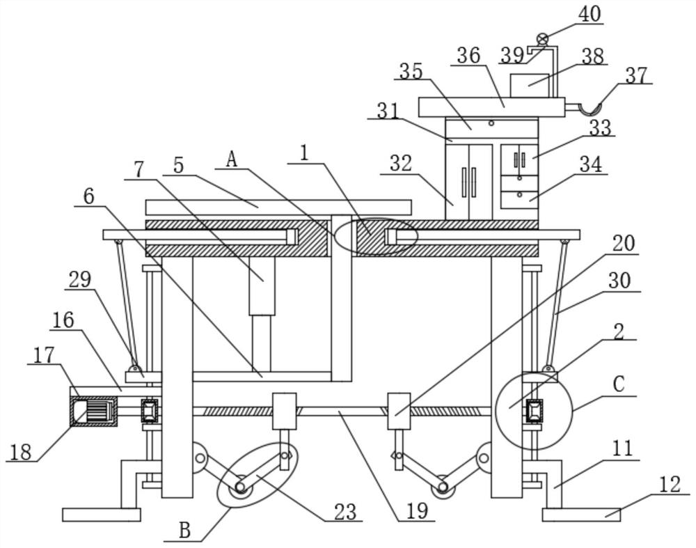
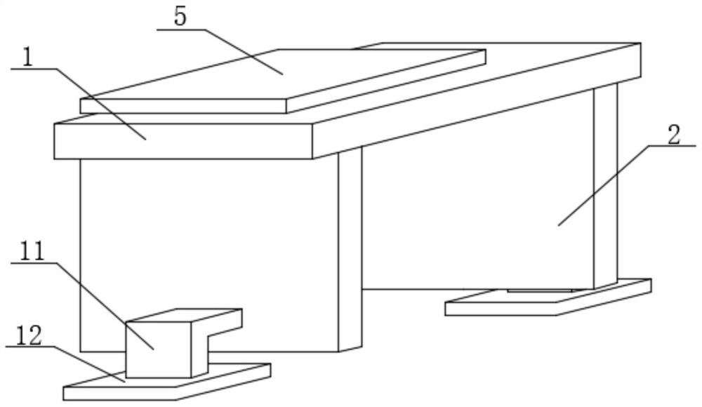
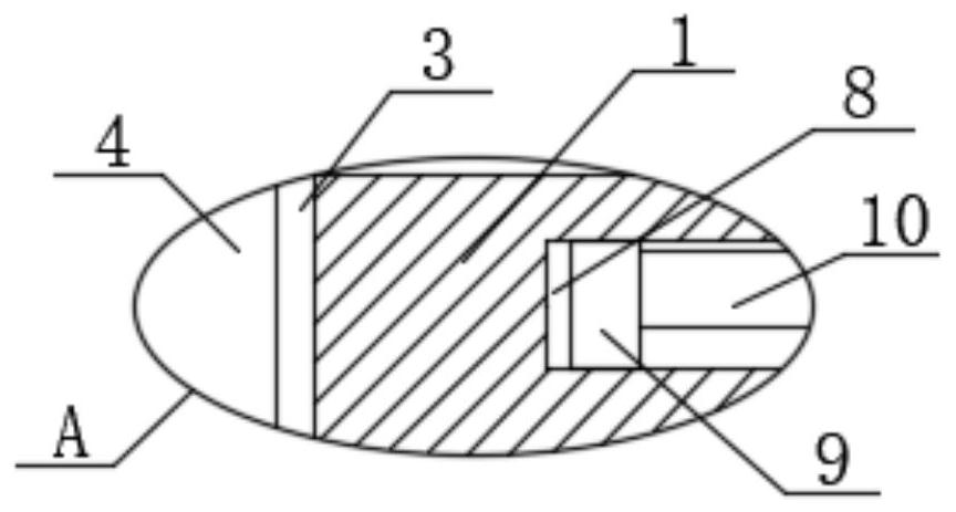
[0028] refer to Figure 1-5 , a marine engineering crane test bench, comprising a mounting plate 1, two vertical plates 2 are symmetrically and fixedly installed on the bottom of the mounting plate 1, a placement plate 5 is slidably mounted on the mounting plate 1, and an adjusting device is fixedly installed on the bottom of the mounting plate 1 , the two vertical boards 2 are slidably installed with support devices, the two vertical boards 2 are movably installed with moving devices, the two vertical boards 2 are slidably installed with push devices, and the two vertical boards 2 are slidably installed with two auxiliary boards 10 , the pushing device is movably connected with the two auxiliary boards 10, a driving motor 18 is fixedly installed on one of the two vertical boards 2, and a first screw rod 19 is fixedly installed on the output of the driving motor 18, and a first screw rod 19 is fixedly installed on the first screw rod 19. Two movable blocks 20 are installed on ...

Embodiment 2

[0040] refer to Figure 1-5 , a marine engineering crane test bench, comprising a mounting plate 1, two vertical plates 2 are symmetrically and fixedly installed on the bottom of the mounting plate 1, a placement plate 5 is slidably mounted on the mounting plate 1, and an adjusting device is fixedly installed on the bottom of the mounting plate 1 , the two vertical boards 2 are slidably installed with support devices, the two vertical boards 2 are movably installed with moving devices, the two vertical boards 2 are slidably installed with push devices, and the two vertical boards 2 are slidably installed with two auxiliary boards 10 , the pushing device is movably connected with the two auxiliary boards 10, a driving motor 18 is fixedly installed on one of the two vertical boards 2, and a first screw rod 19 is fixedly installed on the output of the driving motor 18, and a first screw rod 19 is fixedly installed on the first screw rod 19. Two movable blocks 20 are installed on ...


PUM


Abstract

The invention belongs to the technical field of test benches, particularly relates to an ocean engineering crane test bench, and aims to solve the problems that an existing test bench cannot be subjected to simple height adjustment, the operation space is limited, the use efficiency of the test bench is greatly reduced, and the simulation progress is influenced. The ocean engineering crane test bench comprises a mounting plate; two vertical plates are symmetrically and fixedly mounted at the bottom of the mounting plate, a placing plate is slidably mounted on the mounting plate, an adjusting device is fixedly mounted at the bottom of the mounting plate, a supporting device is slidably mounted on the two vertical plates, a moving device is movably mounted on the two vertical plates, and a pushing device is slidably mounted on the two vertical plates. Two auxiliary plates are symmetrically installed on the mounting plate in a sliding mode, and the pushing device is movably connected with the two auxiliary plates. The ocean engineering crane test bench is convenient to use, the height can be simply adjusted, the ocean engineering crane test bench can be moved according to needs, meanwhile, the operation space can be enlarged, and the use efficiency is effectively improved.

Description

technical field [0001] The invention relates to the technical field of test benches, in particular to an ocean engineering crane test bench. Background technique [0002] The test bench is suitable for related vibration tests of auto parts, electronics, furniture, gifts, ceramics, packaging and other products. In the manufacturing plant of marine engineering cranes, it is generally necessary to simulate the situation of working on a ship, so a special test bench is required. meet the test purpose. [0003] However, the existing test bench cannot perform simple height adjustment, and the operating space is limited, which greatly reduces its use efficiency and affects the simulation progress. Contents of the invention [0004] The object of the present invention is to solve the shortcomings of existing test benches that cannot be easily adjusted in height, and the operating space is limited, which greatly reduces its use efficiency and affects the simulation progress, and p...

Claims


Application Information

Patent Timeline
Patent Type & Authority Applications(China)
IPC IPC(8): B01L9/02
CPCB01L9/02B01L2300/06
Inventor 彭宏宽
Owner 彭宏宽
Why Eureka
Try Eureka