High-precision tooth dividing machine

A gear dividing machine and high-precision technology, which is applied in the tool manufacturing, feeding device, and manufacturing tool of the sawing machine device, can solve the problems of low degree of automation, low positioning accuracy and positioning efficiency, and asymmetric left and right teeth. High degree of automation, compact structure, and the effect of improving quality

Active Publication Date: 2021-12-10
NINGBO CHEERY GARDEN TOOLS
View PDF8 Cites 1 Cited by
  • Summary
  • Abstract
  • Description
  • Claims
  • Application Information

AI Technical Summary

Problems solved by technology

[0004] 1. The existing gear splitting machine needs manual positioning of the band saw blade, the degree of automation is low, and the positioning accuracy and positioning efficiency are also low;
[0005] 2. When the size of the sawtooth or the way of dividing the teeth changes (that is, the order and combination of fixed teeth, right helical teeth and left helical teeth change), the mold needs to be replaced, which not only increases the production and processing costs of the mold , it is very inconvenient to disassemble and assemble the mold;
[0006] 3. Through the interaction between the upper mold and the lower mold to divide the teeth, the band saw blade is prone to the problem of asymmetry between the left and right division teeth, which makes the quality of the division teeth unsatisfactory.

Method used


Image

  • High-precision tooth dividing machine
  • High-precision tooth dividing machine
  • High-precision tooth dividing machine

Examples


Embodiment Construction

[0035] The present invention will be further described below in conjunction with the accompanying drawings.

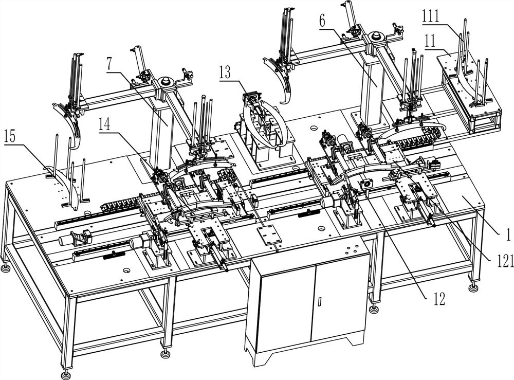
[0036] Such as Figure 1-11 As shown, a high-precision gear dividing machine includes a workbench 1, and the workbench 1 is provided with a loading station 11, a gear dividing station 12, a turning station 13, a gear dividing station 2 14 and a blanking station. Station 15.

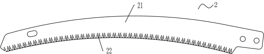
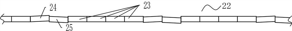
[0037] Here, for the convenience of description, the length direction of the band saw blade 2 is the X-axis direction, the width direction of the band saw blade 2 is the Y-axis direction, and the thickness direction of the band saw blade 2 is the Z-axis direction. 22 are curved saw structures with radians, and of course the gear splitter is also suitable for straight saw-like band saw blades 2 .

[0038]The loading station 11 is fixedly arranged on the right end of the workbench 1, and the unloading station 15 is fixedly arranged on the left end of the workbench 1. The feeding station 11 is used...


PUM


Abstract

The invention discloses a high-precision tooth dividing machine which comprises a workbench, and the workbench is provided with a feeding station, a first tooth dividing station, an overturning station, a second tooth dividing station and a discharging station; the first tooth dividing station and the second tooth dividing station are each provided with a platen, a positioning mechanism, a clamping mechanism, a double-shaft sliding table and a knocking mechanism; a band saw blade is driven by the double-shaft sliding table to move to a tooth knocking position of the knocking mechanism in a sawtooth arrangement or / and interval mode; and the workbench comprises a first grabbing mechanism, a second grabbing mechanism and a turnover mechanism. A first grabbing mechanism grabs the band saw blade on the feeding station and places the band saw blade on the first tooth dividing station, the first grabbing mechanism grabs the band saw blade on the first tooth dividing station and places the band saw blade on the overturning station, the turnover mechanism turns over the band saw blade on the overturning station, and a second grabbing mechanism grabs the band saw blade on the overturning station and places the band saw blade on the platen of the second tooth dividing station, and grabs the band saw blade on the second tooth dividing station and places the band saw blade on the discharging station, so that automatic feeding, positioning, tooth dividing and discharging are achieved, and meanwhile the tooth dividing precision of the tooth dividing machine is high.

Description

technical field [0001] The invention relates to the technical field of band saw blade processing equipment, in particular to a high-precision gear dividing machine. Background technique [0002] To divide the teeth is to deflect the sawtooth 22 of the band saw blade 2 to both sides respectively, so that it is not on a plane, such as Figure 1-2 The band saw blade 2 shown includes a saw back 21 and saw teeth 22 on the saw back 21. The saw teeth 22 are divided into three categories: fixed teeth 23, right oblique teeth 24, and left oblique teeth 25. The fixed teeth 23 and the saw back 21 are in the same position. There is no deflection in the same plane, but the right helical tooth 24 and the left helical tooth 23 are respectively bent to both sides. The divided band saw blade 2 has a cutting edge wider than the thickness of the saw back, so that the saw kerf can be widened to avoid excessive friction between the saw back and the material to be cut when the saw back passes thro...

Claims


Application Information

Patent Timeline
IPC IPC(8): B21D43/02B21D43/10B21D43/14B21D43/20B21D28/02B23D65/02
CPCB21D43/026B21D43/105B21D43/145B21D43/20B21D28/02B23D65/02
Inventor 熊加林
Owner NINGBO CHEERY GARDEN TOOLS
Why Eureka
Try Eureka