Eureka AIR delivers breakthrough ideas for toughest innovation challenges, trusted by R&D personnel around the world.

Device for automatically assembling flange plate and shaft sleeve

An automatic assembly and shaft sleeve technology, which is applied in metal processing, metal processing equipment, manufacturing tools, etc., can solve the problems of insufficient tightness of flange plate and shaft sleeve assembly, poor assembly effect, low assembly efficiency, etc., and achieve assembly effect commission , small size, easy adjustment and repair

Pending Publication Date: 2021-12-10
浙江精锐智能传动有限公司
View PDF0 Cites 0 Cited by
  • Summary
  • Abstract
  • Description
  • Claims
  • Application Information

AI Technical Summary

Problems solved by technology

[0002] The assembly of the flange and the shaft sleeve is usually done manually, which is not only time-consuming and laborious, but also the assembly of the flange and the shaft sleeve is not tight enough, the assembly effect is poor, the assembly efficiency is low, and the production cost is high. There is an urgent need for an automatic assembly flange Disk and sleeve device to fill the gap in the industry

Method used


Image

  • Device for automatically assembling flange plate and shaft sleeve
  • Device for automatically assembling flange plate and shaft sleeve
  • Device for automatically assembling flange plate and shaft sleeve

Examples


Embodiment Construction

[0020] The present invention will be further described below in conjunction with accompanying drawing:

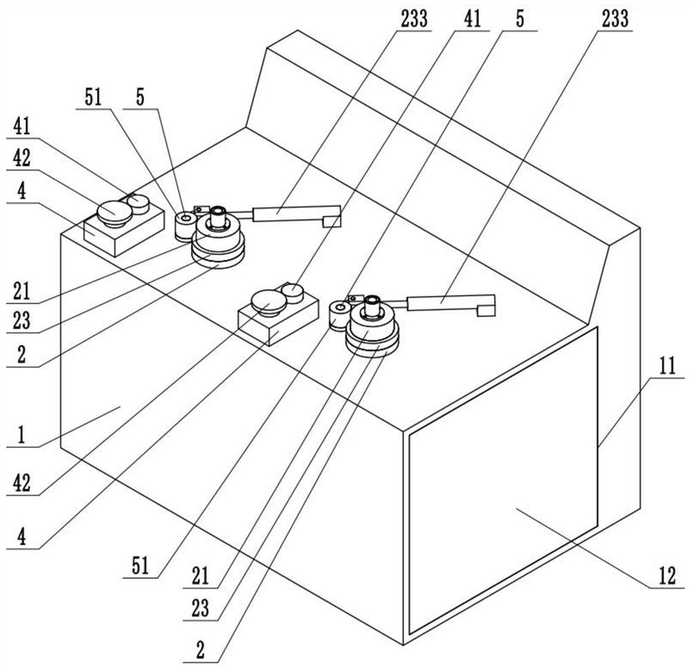
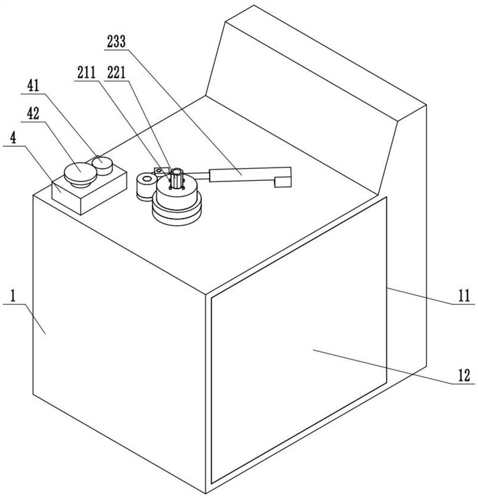
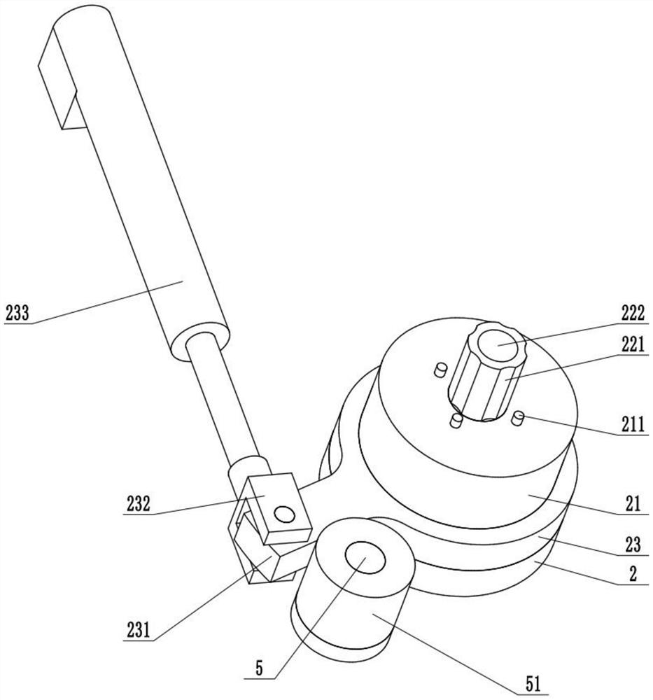
[0021] like figure 1 and Figure 4-5 As shown: a device for automatically assembling flanges and shaft sleeves in this embodiment, including a housing 1, a mounting seat 2 installed on the upper end of the housing 1, a clutch 33 is installed inside the housing 1, and a clutch 33 is installed on the inner side of the housing 1. Motor 36 is arranged, and motor 36 can make clutch 33 flywheels rotate, and clutch 33 output shaft upper ends are fixedly connected with rotating shaft 22, and rotating shaft 22 outer sides are slidably connected with pressure ring 3, and pressure ring 3 lower ends are fixedly connected with clutch 33 pressure plates, pressure ring 3 outsides Fixedly connected with a fixed frame 31, the left and right ends of the lower side of the fixed frame 31 are fixedly connected with a second cylinder 32, the second cylinder 32 is fixedly connected inside the ho...


PUM


Abstract

The invention relates to a device for automatically assembling a flange plate and a shaft sleeve. The device comprises a shell, a mounting seat arranged at the upper end of the shell, a clutch mounted on the inner side of the shell, a motor mounted on the inner side of the shell, a rotating shaft connected to the upper end of an output shaft of the clutch, a pressing ring slidably connected to the outer side of the rotating shaft, and a fixing frame connected to the outer side of the pressing ring, wherein left and right ends of the lower side of the fixing frame are connected with second gas cylinders which are connected to the inner side of the shell; and the rotating shaft extends out of the shell; the upper end of the mounting base is rotatably connected with a placement disc, the rotating shaft sequentially penetrates through the mounting base and the placement disc, the upper end of the rotating shaft is connected with a fixing shaft, the outer side shape of the fixing shaft is matched with the inner wall of the shaft sleeve, and the outer side of the fixing shaft is provided with a positioning column connected to the upper end of the placement disc; and the size of the positioning column is matched with that of a hole in the flange plate. The device is simple in structure, convenient to adjust and repair, small in overall dimension, good in wear resistance, sufficient in heat dissipation capacity, convenient and labor-saving to operate, remarkable in assembly effect, longer in service life, more stable in operation and lower in noise.

Description

technical field [0001] The invention relates to the field of automatic assembly devices, in particular to a device for automatically assembling flanges and shaft sleeves. Background technique [0002] The assembly of the flange and the shaft sleeve is usually done manually, which is not only time-consuming and laborious, but also the assembly of the flange and the shaft sleeve is not tight enough, the assembly effect is poor, the assembly efficiency is low, and the production cost is high. There is an urgent need for an automatic assembly flange The device of disk and sleeve to fill the gap in the industry. Contents of the invention [0003] The present invention aims to solve the above-mentioned problems in the prior art, and provides a device for automatically assembling flanges and shaft sleeves, which not only can automatically assemble flanges and shaft sleeves, but also has a simple structure and low cost. [0004] The technical solution adopted by the present inven...

Claims


Application Information

Patent Timeline
Patent Type & Authority Applications(China)
IPC IPC(8): B23P19/00B23P19/04
CPCB23P19/00B23P19/04
Inventor 赵晨阳华秀军雷林和
Owner 浙江精锐智能传动有限公司
Why Eureka
Eureka Blog
Learn More