
Milling device assembly

A milling device and assembly technology, applied to stone processing tools, work accessories, manufacturing tools, etc., can solve the problems of coolant leakage, poor waterproof effect on the upper end of the motor shaft, and heavy maintenance workload of the secondary transmission mechanism. To achieve the effect of improving stability

Pending Publication Date: 2021-12-10
中山佳朗精密机械有限公司
View PDF1 Cites 0 Cited by
  • Summary
  • Abstract
  • Description
  • Claims
  • Application Information

AI Technical Summary

Problems solved by technology

[0002] During the use of glass and stone drilling machines in the prior art, the drill parts need to use a secondary transmission mechanism (such as a belt drive) to drive the drill parts to perform rotary drilling. The structure of its transmission mechanism is complicated, and the maintenance workload of the subsequent secondary transmission mechanism is large and inconvenient. At the same time, the radial runout of the milling cutter is large, and the machining accuracy of the milling cutter is not high. coolant leak
[0003] The application number is CN202020068881.1 and the name is: A Chinese utility model of an integrated high-precision hydroelectric spindle structure. A hydroelectric spindle structure is disclosed. The hydroelectric spindle structure It is simple and has high drilling precision and good anti-coolant leakage effect. However, when the spindle structure is working, it is still easy for coolant to leak into the lower bearing through the surface of the spindle core, which affects the service life of the lower bearing.

Method used


Image

  • Milling device assembly
  • Milling device assembly
  • Milling device assembly

Examples


Embodiment Construction

[0021] The specific embodiments of the present invention will be further described below in conjunction with the accompanying drawings, but the present invention is not limited.

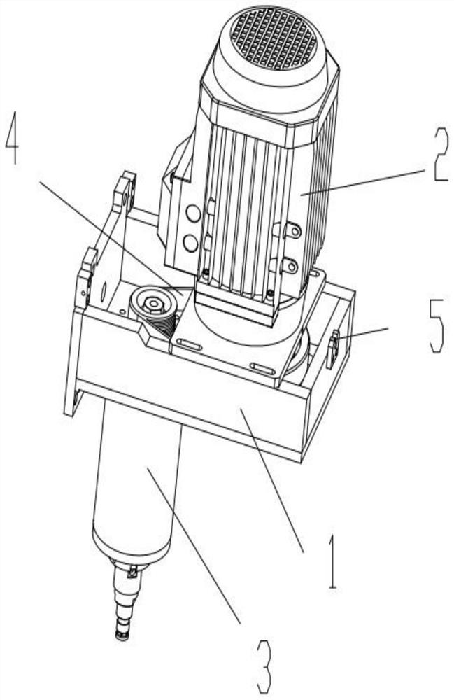
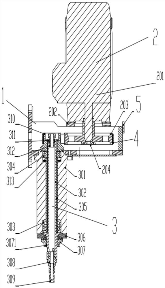
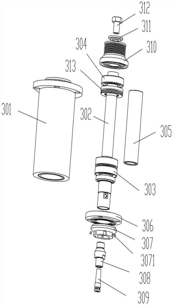
[0022] figure 1 , figure 2 A milling device assembly is shown, including a grinding head support 1, a milling rotation device 2, a milling device 3 and a multi-wedge belt 4, the milling device 3 is fixed on the grinding head support 1, and the multi-wedge belt 4 is connected to the milling rotation Device 2, milling device 3 and transfer rotation, milling device 3 includes main shaft sleeve 301, main shaft core 302, lower end bearing 303, upper end bearing 304, spacer sleeve 305, first gland 306, labyrinth cover 307, drill sleeve 308, milling Knife 309, pulley 310, pressure pad 311 and connector 312, the main shaft sleeve 301 is fixed on the grinding head support 1, the upper end and lower end of the inner cavity of the main shaft sleeve 301 are respectively equipped with an upper end bearing 304, ...


PUM


Abstract

The invention discloses a milling device assembly which comprises a grinding head support, a milling rotating device, a milling device and a multi-wedge belt, the milling device is fixed on the grinding head support, and the multi-wedge belt is connected with the milling rotating device and the milling device and transmits rotation. The milling device comprises a main shaft sleeve, a main shaft core, a lower end bearing, an upper end bearing, a spacer bush, a first gland, a labyrinth cover, a drill bushing, a milling cutter, a belt wheel, a pressure pad and a connector, the main shaft core sequentially penetrates through the upper end bearing, the spacer bush, the lower end bearing and the first gland, the two ends of the main shaft core are exposed out of the two ends of the main shaft sleeve, and the belt wheel is fixed to the upper end of the main shaft core in an interference fit mode; and the connector penetrates through the pressure pad to be in threaded connection with an inner hole of the main shaft core, the pressure pad presses the belt wheel, the labyrinth cover is in threaded connection with the lower end of the main shaft core and is in adaptive buckling rotary connection with the first gland, the drill bushing is connected with the lower end of the main shaft core, and the milling cutter is connected with the drill bushing. Cooling liquid is effectively prevented from permeating into the bearing at the lower end from the surface of the main shaft core, and meanwhile the stability of milling cutter machining operation is improved.

Description

technical field [0001] The invention relates to the technical field of processing brittle plates (glass, stone, etc.), in particular to a milling device assembly. Background technique [0002] The glass and stone drilling machines of the prior art need to use a secondary transmission mechanism (such as a belt drive) to drive the drill bit to perform rotary drilling during use. The structure of the transmission mechanism is complex, and the maintenance workload of the subsequent secondary transmission mechanism is large. It is inconvenient, and its milling cutter radial runout is big simultaneously, and milling cutter machining accuracy is not high, and the waterproof effect of the motor shaft upper end of its internal conduction is not good, and coolant leakage easily takes place. [0003] The application number is CN202020068881.1 and the name is: A Chinese utility model of an integrated high-precision hydroelectric spindle structure. A hydroelectric spindle structure is di...

Claims


Application Information

Patent Timeline
IPC IPC(8): B28D1/18B28D7/00
CPCB28D1/18B28D7/005B28D7/00
Inventor 李锋熊仕科
Owner 中山佳朗精密机械有限公司
Learn More