Connecting structure for binding belt and hook

A technology of connecting structure and binding belt, applied in the field of connecting structure between binding belt and hook, can solve the problems of unable to replace the hook, unable to replace the hook, increase the user's input cost, etc., to achieve a large market promotion prospect, low manufacturing cost, practical strong effect

Pending Publication Date: 2021-12-10
ZHEJIANG TOPSUN LOGISTIC CONTROL CO LTD
View PDF22 Cites 0 Cited by
  • Summary
  • Abstract
  • Description
  • Claims
  • Application Information

AI Technical Summary

Problems solved by technology

Although the connection method between the binding belt and the hook is convenient to manufacture, and can ensure that the hook and the binding belt are firmly connected and the binding process is safe, the hook cannot be replaced
However, different occasions usually require the use of different styles of hooks, and the connection between the existing binding straps and hooks cannot be replaced because the hooks cannot be replaced, so the user needs to be equipped with multiple sets of binding devices with different hook styles to meet different occasions. The demand for fixed goods will increase the user's input cost virtually.

Method used


Image

  • Connecting structure for binding belt and hook
  • Connecting structure for binding belt and hook
  • Connecting structure for binding belt and hook

Examples


Embodiment 1

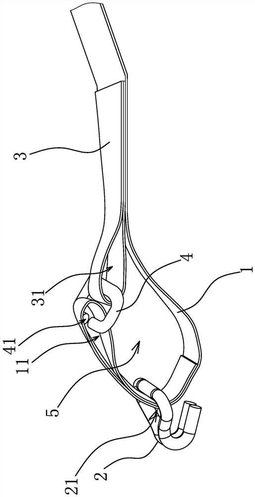
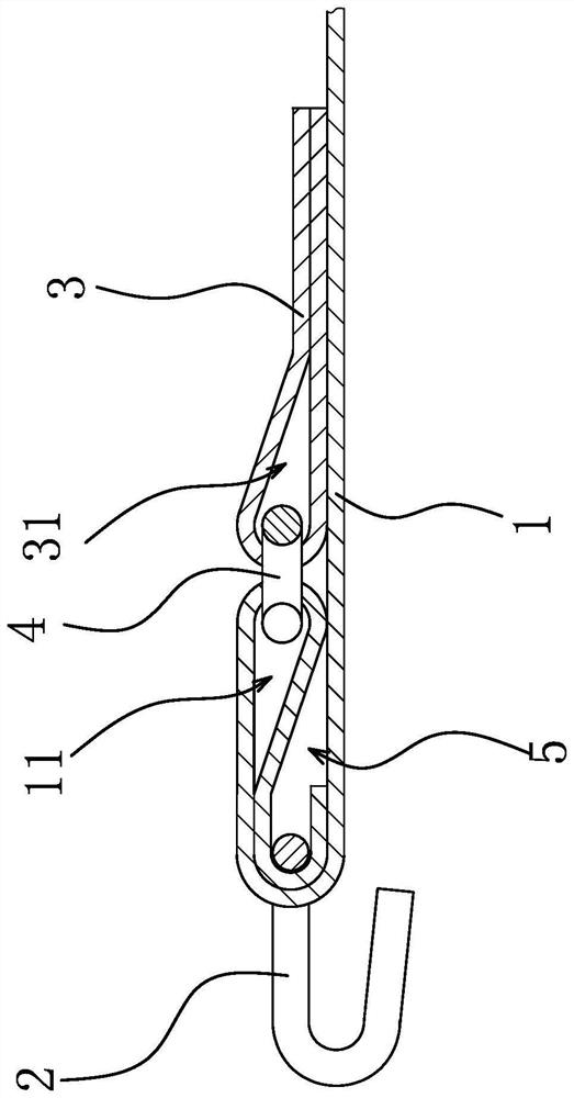
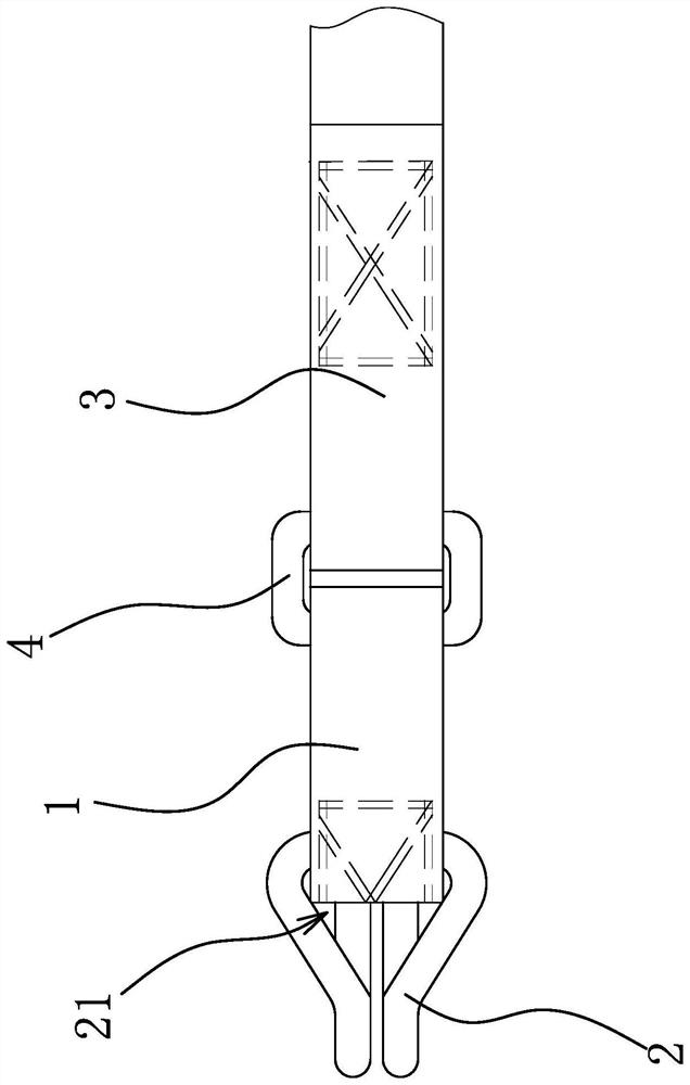
[0038] Such as Figure 1 to Figure 3 As shown, the connection structure between the binding belt and the hook includes a main belt body 1, an auxiliary belt body 3 and a hook 2, the end of the main belt body 1 has a closed socket ring 11, and the auxiliary belt body 3 is fixedly connected to the main belt body 1, the end of the auxiliary belt body 3 also has a closed sleeve ring 2 31, and the sleeve ring 11 and the sleeve ring 2 31 are connected through a connecting ring 4 with a gap 41, thereby forming a large ring 5 , the hook 2 is threaded on the large ring 5 .

[0039] Specifically, continue to refer to Figure 1 to Figure 3 After the end of the main belt body 1 is folded in half along the length direction, the folded part is partially sewed to form the above-mentioned sleeve ring 11, and the binding belt is tightened by the hook 2 to form the suture of the hook 2 and the end of the main belt body 1 when tensioned. Part contact, because the suture part is a double-layer ...

Embodiment 2

[0043] The structure and principle of this embodiment are basically the same as that of Embodiment 1, the difference is that: Figure 9 As shown, the connecting ring 4 is an integrally formed circular metal ring. The connecting ring 4 is an integrally formed circular metal ring, which is more convenient to manufacture and can reduce manufacturing costs. At the same time, the connecting ring 4 has a relatively high tensile strength due to the integral forming, and is not easily deformed during the binding process.

Embodiment 3

[0045] The structure and principle of this embodiment are basically the same as that of the first embodiment, except that the length of the inner hole of the connecting ring 4 is equal to the width of the main belt body 1 and the auxiliary belt body 3 .


PUM


Abstract

The invention provides a connecting structure for a binding belt and a hook, belongs to the technical field of logistics transportation equipment, and solves the problem that a hook for a binding belt is difficult to replace in the prior art. The connecting structure for the binding belt and the hook comprises a main belt body and the hook. A first closed sleeving ring is arranged at the end of the main belt body, an auxiliary belt body is fixedly connected to the main belt body, a second closed sleeving ring is also arranged at the end of the auxiliary belt body, and the first sleeving ring and the second sleeving ring are connected through a connecting ring with a notch to form a large ring, and the hook is connected to the large ring in a penetration manner. The hook is convenient to replace on the basis of ensuring the binding safety, and meanwhile, the hook has the advantages of low manufacturing cost and high practicability.

Description

technical field [0001] The invention belongs to the technical field of logistics transportation equipment, and relates to a connection structure between a binding belt and a hook. Background technique [0002] During the transportation of goods, it is often necessary to tie up the goods to prevent the goods from falling or moving. The binding device is a device that can firmly bind the goods on the car, and has been widely used in the current logistics field. [0003] The binding device usually includes a binding belt for binding goods and a hook connected to the end of the binding belt. At present, the connection between the binding belt and the hook is to fold the end of the binding belt through the hook hole of the hook and fold it in half. Fastened with sutures. [0004] Such as a structurally improved binder disclosed in Chinese patent literature (application number: CN200820180137.X; publication number: CN201325603). Although the connection method between the bindin...

Claims


Application Information

Patent Timeline
IPC IPC(8): B65D63/16B65D63/14F16G11/08B60P7/06
CPCB65D63/16B65D63/14F16G11/08B60P7/06B65D2563/103B65D2563/101
Inventor 阮云波朱正中
Owner ZHEJIANG TOPSUN LOGISTIC CONTROL CO LTD
Why Eureka
Try Eureka