Supercharge Your Innovation With Domain-Expert AI Agents!

Filtration equipment

A technology of filtration equipment and filtration materials, applied in filtration and separation, membrane filters, gravity filters, etc., can solve problems such as small effective filtration surface area, and achieve the effect of improving work efficiency, reducing time, and reducing the number of backwash operations

Inactive Publication Date: 2004-02-11
永冈忠义
View PDF3 Cites 1 Cited by
  • Summary
  • Abstract
  • Description
  • Claims
  • Application Information

AI Technical Summary

Problems solved by technology

[0005] More importantly, prior art filter devices have a relatively small effective filter surface area compared to the size of a vessel containing multiple layers of filter material

Method used


Image

  • Filtration equipment
  • Filtration equipment
  • Filtration equipment

Examples


Embodiment Construction

[0049] Figure 1-5 One embodiment of a filtration device manufactured according to the invention is described.

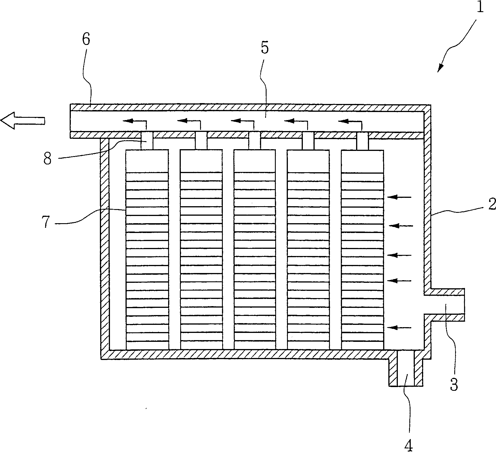
[0050] figure 1 The structure of the filter device 1 is schematically depicted. The container 2 is a box-like structure having a treatment liquid inlet 3 at the lower part of one side thereof and a discharge port 4 at the bottom thereof. The discharge port 4 is normally closed and is opened when solid foreign particles accumulated at the bottom of the container 2 are to be removed. The upper part of the container 2 is made as a process liquid discharge pipe 5 with an outlet 6 .

[0051] Within the container 2 are located one or more pre-filled annular multi-layer screen packs (five screen packs in the illustrated embodiment), which packs are identified by reference numeral 7 . Each screen assembly 7 has an outlet 8 at its upper portion, and the outlet 8 communicates with the treatment liquid discharge pipe 5 .

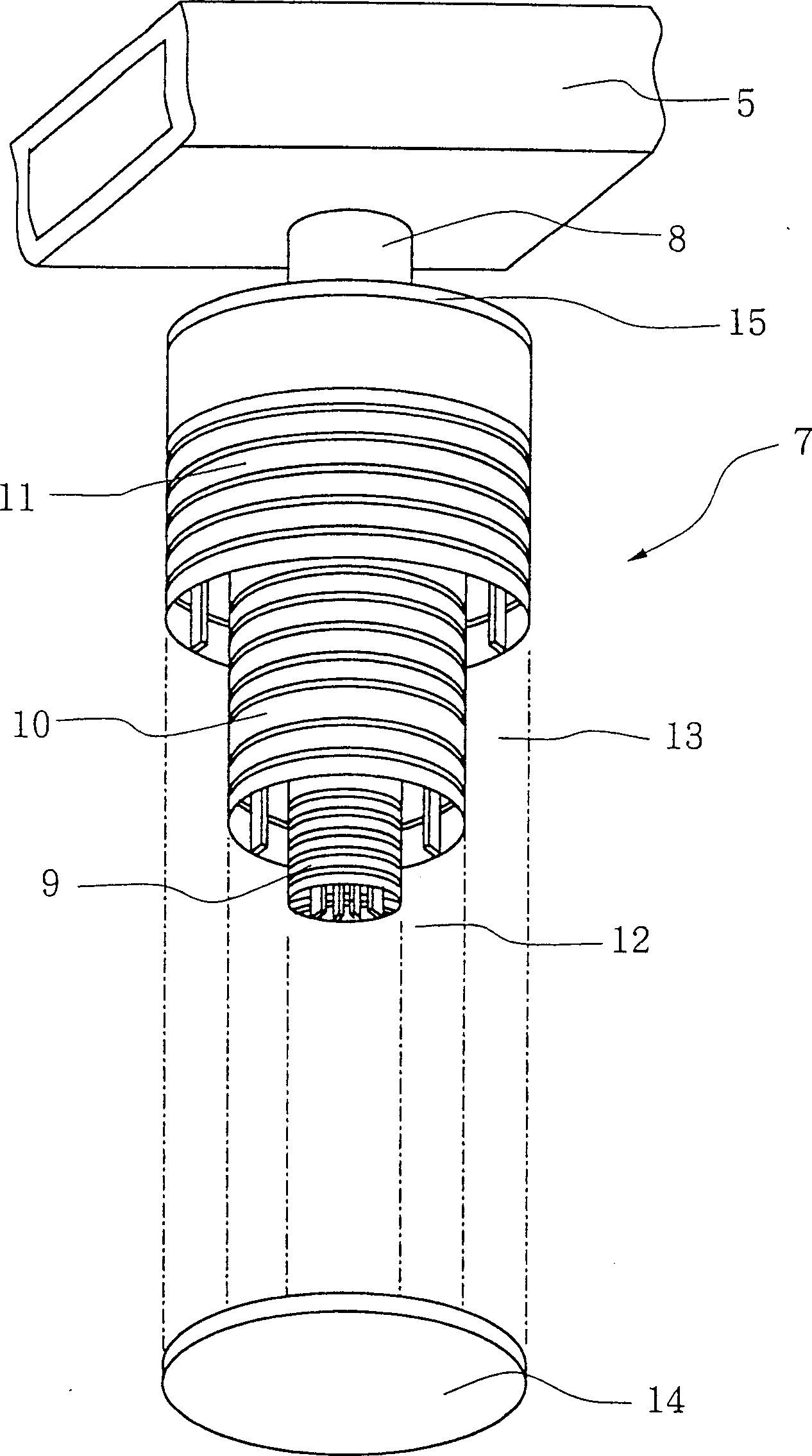
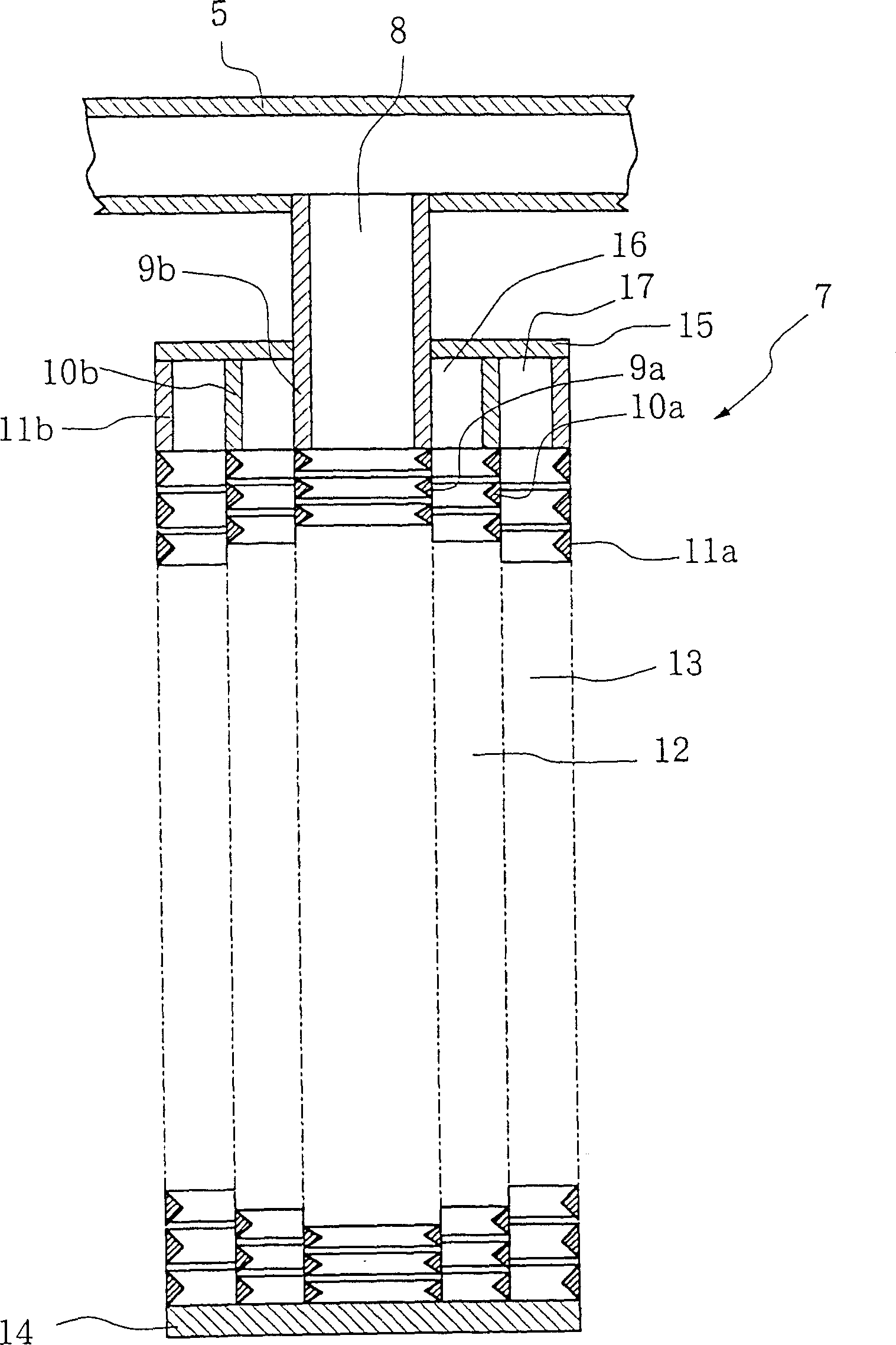
[0052] figure 2 An example of a pre-packed ann...


PUM


Abstract

A filtering device includes a container having an inlet for introducing liquid to be treated, an annular multi-layered prepacked screen assembly provided in the container and having an outlet for treated liquid. The screen assembly includes three or more cylindrical screens having different diameters and bieng coaxially disposed in the container with their axes extending vertically in the container. An anulus is formed between the respective cylindrical screens. Two or more different filter materials performing different filtering functions are filled one in each of the annuluses between the cylindrical screens.

Description

technical field [0001] The present invention relates to a filter device, and more particularly to a filter device suitable for submersion in a treatment liquid for fine filtration. Treated liquids include common water, drinking water, river water, pond water and other various liquids. Background technique [0002] A filter device known in the art comprises multiple layers of different types of filter material arranged in a single container through which the process liquid is passed for different filtration operations. Figure 19 An example of such a prior art filtering device is given. In this prior art filtering apparatus, the treatment liquid is introduced into the container a through the inlet b provided at the upper part of the container a. The treatment liquid is distributed on the upper filter material d through the distributor c. The upper layer of filter material d is composed of coarse anthracite, and impurities with relatively large diameters in the treatment liq...

Claims


Application Information

Patent Timeline
IPC IPC(8): B01D29/46B01D21/34B01D24/08B01D27/02B01D29/11B01D29/15B01D29/33B01D33/06B01D35/147
CPCB01D2201/188B01D2201/0407B01D35/147B01D29/15B01D2201/0484B01D29/46B01D29/52B01D29/58B01D29/68B01D29/11B01D29/33
Inventor 永冈忠义
Owner 永冈忠义
Features
  • R&D
  • Intellectual Property
  • Life Sciences
  • Materials
  • Tech Scout
  • Unparalleled Data Quality
  • Higher Quality Content
  • 60% Fewer Hallucinations
Learn More