SCR fault diagnosis method and device
A fault diagnosis and detection technology, which is applied in the diagnosis device of exhaust treatment device, electronic control of exhaust treatment device, complex mathematical operation, etc., can solve the problems of easy false alarm and no alarm, etc. Diagnosis accuracy and accuracy, and the effect of improving user experience
- Summary
- Abstract
- Description
- Claims
- Application Information
AI Technical Summary
Problems solved by technology
Method used
Image

Examples
Embodiment Construction
[0045] Reference will now be made in detail to the exemplary embodiments, examples of which are illustrated in the accompanying drawings. When the following description refers to the accompanying drawings, the same numerals in different drawings refer to the same or similar elements unless otherwise indicated. The implementations described in the following exemplary examples do not represent all implementations consistent with the present disclosure. Rather, they are merely examples of apparatuses and methods consistent with aspects of the present disclosure as recited in the appended claims.
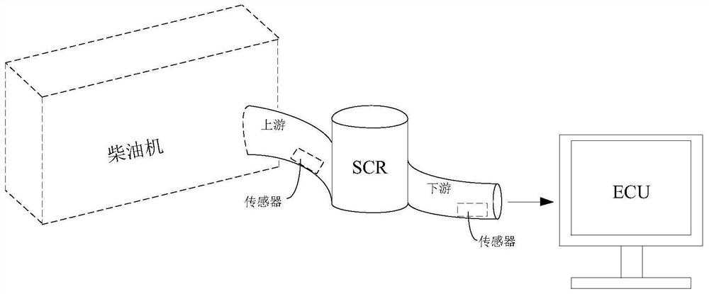
[0046] Diesel engines will produce harmful nitrogen oxides (NO X ), in order to meet the statutory emission requirements of diesel engines, most of the aftertreatment systems of existing diesel engines are equipped with selective catalytic reduction units (Selective Catalystic Reduction, SCR). The selective catalytic reduction unit reduces nitrogen oxides into harmless nitrogen by spr...
PUM
 Abstract
Description
Claims
Application Information
 - Generate Ideas
- Intellectual Property
- Life Sciences
- Materials
- Tech Scout
- Unparalleled Data Quality
- Higher Quality Content
- 60% Fewer Hallucinations
Browse by: Latest US Patents, China's latest patents, Technical Efficacy Thesaurus, Application Domain, Technology Topic, Popular Technical Reports.
© 2025 PatSnap. All rights reserved.Legal|Privacy policy|Modern Slavery Act Transparency Statement|Sitemap|About US| Contact US: help@patsnap.com