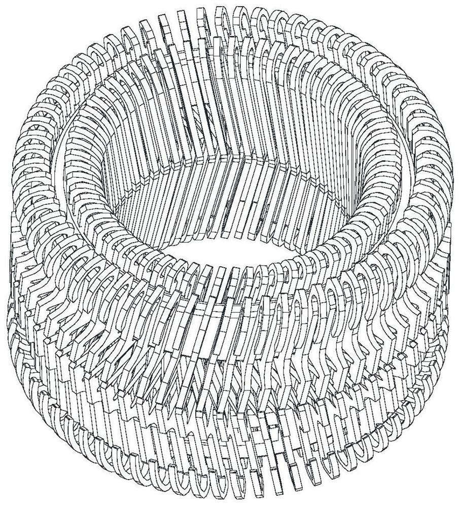
Contact terminal, electric connector and electronic equipment
A technology of contact terminals and electrical connectors, which is applied in the direction of connection, contact parts, and parts of connection devices, etc. It can solve the problems of large wire winding, small terminal holding force, and increased winding density of wire springs. , to achieve the effect of increasing current-carrying capacity, increasing terminal current-carrying, and reducing contact resistance
- Summary
- Abstract
- Description
- Claims
- Application Information
AI Technical Summary
Problems solved by technology
Method used
Image
Examples
Embodiment 1
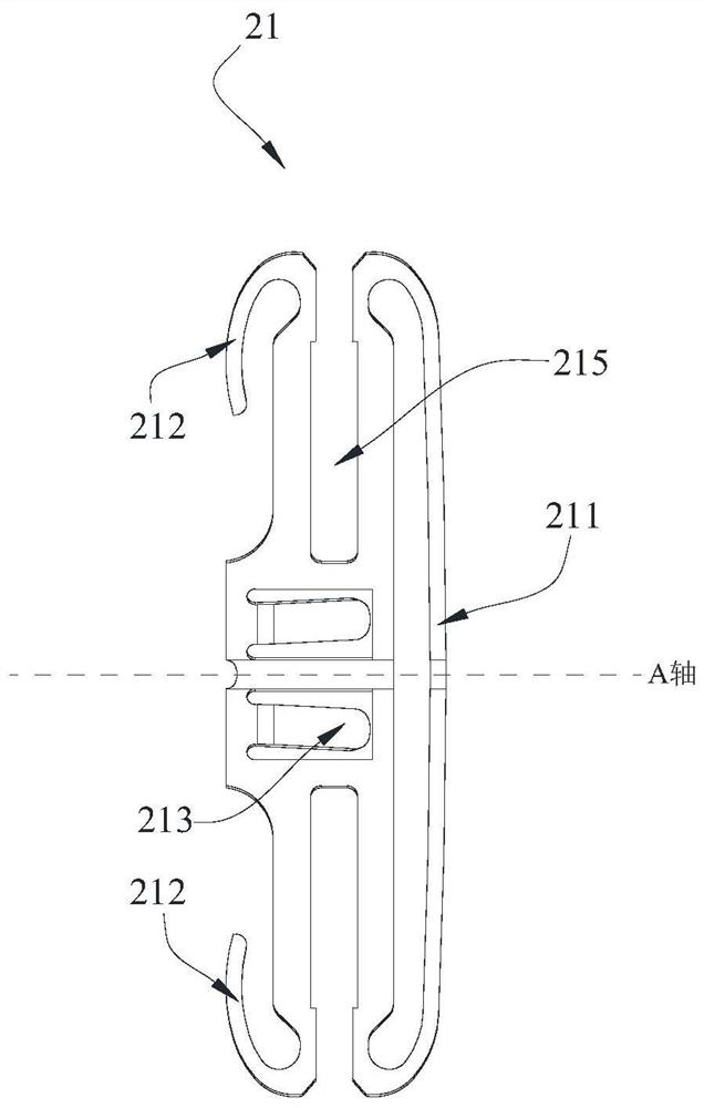
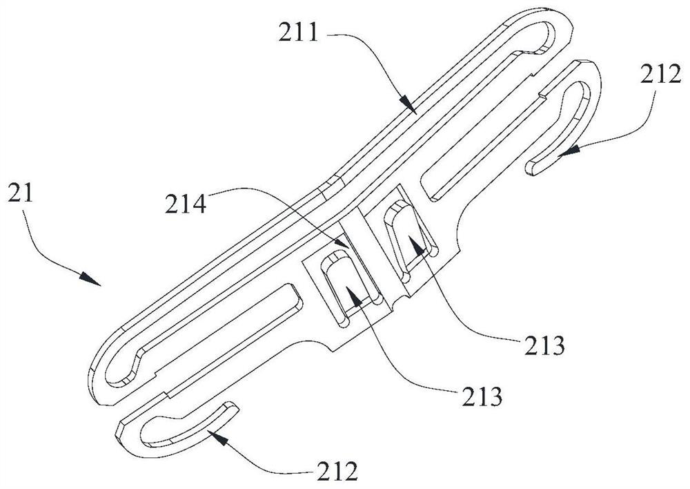
[0051] Contact terminals, which are used in electrical connectors. Please refer to Figure 1-5 As shown, the contact terminal mainly includes a first contact piece 21 and a first bracket 30 . Wherein, the first contact piece 21 is provided with a first contact arm 211 and a second contact arm 212, the first contact piece 21 is preferably formed by punching, and the punching direction is perpendicular to the direction of the first contact arm 211 or the second contact arm 212 , that is, the thin edges on both sides of the first contact piece 21 serve as the first contact arm 211 and the second contact arm 212 respectively.
[0052] Using the first contact piece 21 in a stamping manner and the punching direction perpendicular to the direction of the first contact arm 211 or the second contact arm 212 can avoid the problem that the width and spacing of the contact piece cannot be reduced due to factors such as mold manufacturing, and can ensure The insertion and withdrawal forc...
Embodiment 2
[0066] Embodiment 2 shows another structure of the contact terminal. The end surface of the contact terminal which contacts with the male terminal is realized to be a hyperboloid through twisting.
[0067] Please refer to Figure 7-9 As shown, in order to show the distinction, the contact piece in the second embodiment is called the second contact piece 24 (corresponding to the first contact piece in the first embodiment), and the side where the second contact piece 24 is in contact with the male terminal is called the third contact piece. The contact arm 241 (corresponding to the first contact arm in the first embodiment), and the side where the second contact piece 24 is in contact with the main body of the female terminal is called the fourth contact arm 242 (corresponding to the second contact arm in the first embodiment).
[0068] In the second embodiment, the connecting portion between the third contact arm 241 and the fourth contact arm 242 is twisted by a certain angl...
Embodiment 3
[0073] Embodiment 3 shows a structure of an electrical connector. It mainly includes a first connector female terminal 100 . Please refer to Figure 10-13 As shown, it shows a cylindrical first connector female terminal 100 , and the first connector female terminal 100 includes a first female terminal main body 10 , a first contact terminal 20 and a plug 40 .
[0074] Wherein, the first female terminal main body 10 is provided with an accommodating space, the first contact terminal 20 is installed in the accommodating space, and the plug 40 is blocked at the end of the accommodating space, which is used to prevent the first contact terminal 20 from Axial movement in the first female terminal body 10 .
[0075] The first contact terminal 20 may adopt any structural form of the first embodiment or the second embodiment. For example Figure 12 and Figure 13 It shows that using the contact terminal method of Embodiment 1, the bent portion provided on the second contact arm ...
PUM
 Abstract
Description
Claims
Application Information
 - R&D
- Intellectual Property
- Life Sciences
- Materials
- Tech Scout
- Unparalleled Data Quality
- Higher Quality Content
- 60% Fewer Hallucinations
Browse by: Latest US Patents, China's latest patents, Technical Efficacy Thesaurus, Application Domain, Technology Topic, Popular Technical Reports.
© 2025 PatSnap. All rights reserved.Legal|Privacy policy|Modern Slavery Act Transparency Statement|Sitemap|About US| Contact US: help@patsnap.com


