Double-layer DP connector and manufacturing process thereof[

A connector and double-layer technology, which is applied in the field of double-layer DP connectors and its manufacturing process, can solve the problems of high production cost, difficult realization, and disconnection, and achieve ingenious and reasonable design of positioning relationship and assembly method. Good controllability of position accuracy, ensuring the effect of combining reliability

Pending Publication Date: 2021-12-10
FREEPORT GUANGDONG PRECISION IND CO LTD
View PDF0 Cites 0 Cited by
  • Summary
  • Abstract
  • Description
  • Claims
  • Application Information

AI Technical Summary

Problems solved by technology

This kind of production method is difficult to insert the PIN. When inserting the PIN, it is easy to insert bent, skewed or even disconnected, resulting in a high defect rate. Moreover, limited by the precision of the inserting PIN technology, the position accuracy of the terminal in the plastic body It is difficult to control, and it is difficult to guarantee the consistency of PIN quality; when producing DP connectors with high requirements, the production yield is even lower, resulting in high production costs
And, for the double-layer DP connector, because it needs to process the upper-layer DP interface and the lower-layer DP interface, it is more difficult to realize a total of 4 rows of terminals.

Method used


Image

  • Double-layer DP connector and manufacturing process thereof[
  • Double-layer DP connector and manufacturing process thereof[
  • Double-layer DP connector and manufacturing process thereof[

Examples


Embodiment Construction

[0056] Please refer to Figure 1 to Figure 16 As shown, it shows the specific structure of the embodiment of the present invention.

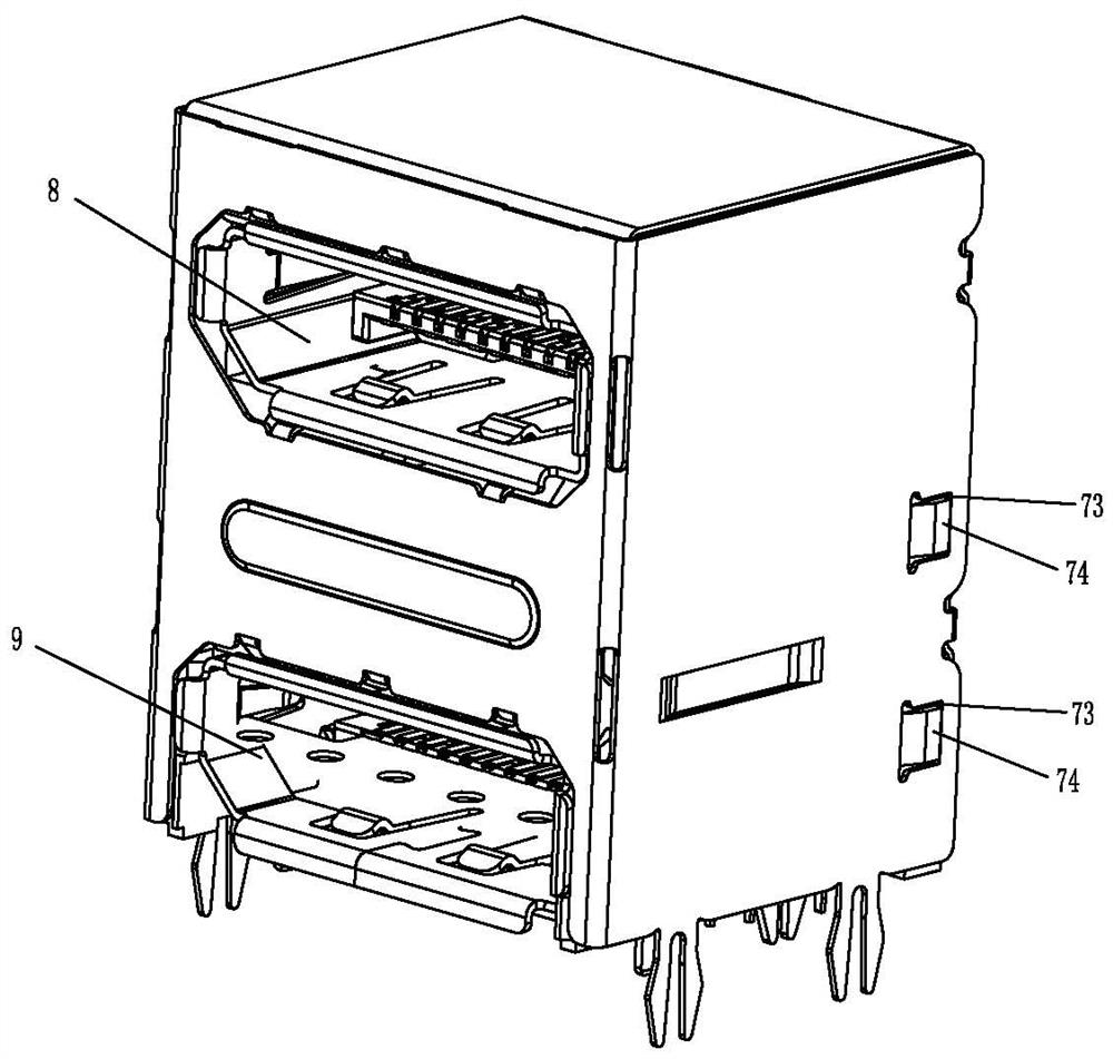
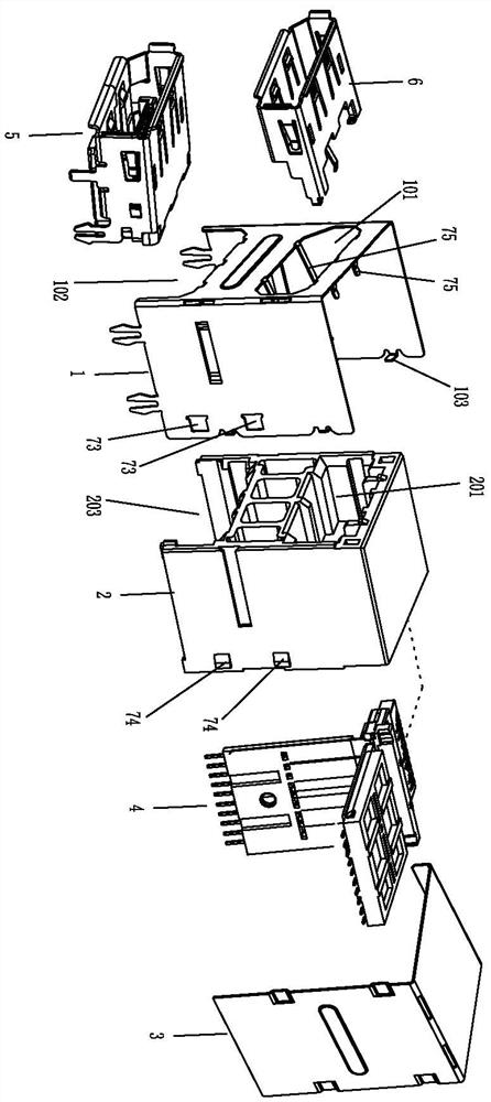
[0057] A double-layer DP connector, including a DP shell 1, a DP plastic body 2, a rear cover 3, an upper DP shell 6, an upper DP Molding component 4, and a lower DP connector module 5; wherein, the DP shell 1 covers Outside the DP plastic body 2, the rear cover 3 is covered on the rear side of the DP plastic body 2 and spliced ​​with the DP shell 1, so as to cover the multiple sides of the DP plastic body 2 (mainly referring to the front, rear, left, right and top, bottom for terminal's solder leg sticking out). The upper DP shell 6 is installed in the upper area of ​​the DP plastic body 2 , the upper DP Molding component 4 is installed in the upper DP shell 6 , and the lower DP connector module 5 is installed in the lower area of ​​the DP plastic body 2 . The upper-layer DP Molding assembly 4 and the upper-layer DP shell 6 form an upper-laye...


PUM


Abstract

The invention discloses a double-layer DP connector and a manufacturing process thereof. The double-layer DP connector comprises a DP shell, a DP plastic body, a rear cover, an upper-layer DP shell, an upper-layer DP Molding assembly and a lower-layer DP connector module; the DP plastic body is covered with the DP shell, the upper-layer DP shell is arranged in the upper section area in the DP plastic body, the upper-layer DP Molding assembly is arranged in the upper-layer DP shell, and the rear cover covers the rear side of the DP plastic body and is spliced with the DP shell; the lower-layer DP connector module is arranged in the lower section area in the DP plastic body; the upper-layer DP Molding assembly and the upper-layer DP shell form an upper-layer DP interface, and an upper-layer DP interface is exposed out of the upper section area of the front side of the DP shell; the lower-layer DP connector module is provided with a lower-layer DP interface, and the lower-layer DP interface is exposed out of the lower section area of the front side of the DP shell. Production and manufacturing of the double-layer DP connector are achieved, meanwhile, the production yield is high, production cost control is facilitated, and the double-layer DP connector is suitable for application and popularization.

Description

technical field [0001] The invention relates to the technology in the field of DP connectors, in particular to a double-layer DP connector and a manufacturing process thereof. Background technique [0002] The DP connector is mainly suitable for connecting a computer and a screen or a computer and a home theater system, which is used as a high-definition digital display interface. The DP connector in the traditional technology is usually a single-layer interface, which includes a metal shell, a plastic body and a 20PIN terminal. During production, the plastic body is obtained by injection molding first, and several terminal slots are arranged in the plastic body. The way of inserting the PIN is inserted into the plastic body, and then the metal shell is wrapped on the outside of the plastic body. This manufacturing method makes it difficult to insert a PIN. When inserting a PIN, it is easy to insert bent, crooked or even inserted, resulting in a high defect rate. Moreover, ...

Claims


Application Information

Patent Timeline
Patent Type & Authority Applications(China)
IPC IPC(8): H01R13/405H01R13/506H01R13/502H01R27/00H01R43/18H01R43/20
CPCH01R13/405H01R13/506H01R13/5025H01R27/00H01R43/18H01R43/20
Inventor 韩林黄磊王钰陶武松陈奇
Owner FREEPORT GUANGDONG PRECISION IND CO LTD
Why Eureka
Try Eureka