Pain relieving device for migraine patients

A migraine and pain relief technology, applied in medical science, hospital beds, hospital equipment, etc., can solve the problems of poor treatment effect and long-term pain relief for patients, and achieve the effects of migraine relief, pain relief, and stability enhancement.

Inactive Publication Date: 2021-12-14
罗义
View PDF1 Cites 0 Cited by
  • Summary
  • Abstract
  • Description
  • Claims
  • Application Information

AI Technical Summary

Problems solved by technology

The nursing massage device for relieving migraine in the above-mentioned patent has the following disadvantages: no targeted massage is performed on the pain site, which makes the treatment effect poor and results in a longer pain relief time for patients

Method used


Image

  • Pain relieving device for migraine patients
  • Pain relieving device for migraine patients
  • Pain relieving device for migraine patients

Examples


Embodiment 1

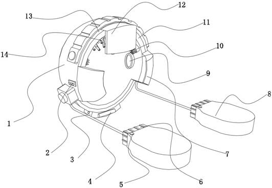
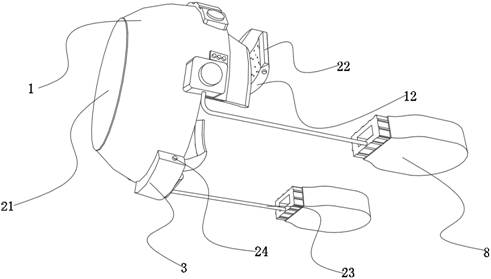
[0033] A pain relief device for migraine sufferers, such as figure 1 , Figure 4 with Image 6As shown, it includes a cover 1, the outer wall of the cover 1 is fixed with a control switch 2 by bolts; the inner wall of the cover 1 is provided with a pain relief structure 1 and a pain relief structure 2, and the pain relief structure 2 includes at least Two targeted relief parts and auxiliary massage parts in opposite positions, the targeted relief part includes an electric slide rail 26, a moving rack 25, a threaded column 29 and a massage component B14, and the electric slide rail 26 is opened on the cover The inner wall of the body 1, the switch control end of the electric slide rail 26 is electrically connected with the control switch 2, the moving rack 25 is slidably connected to the inner wall of the electric slide rail 26 through a slider, and the outer wall of the moving rack 25 is engaged with a rotating connection The gear 27 on the inner wall of the cover body 1, th...

Embodiment 2

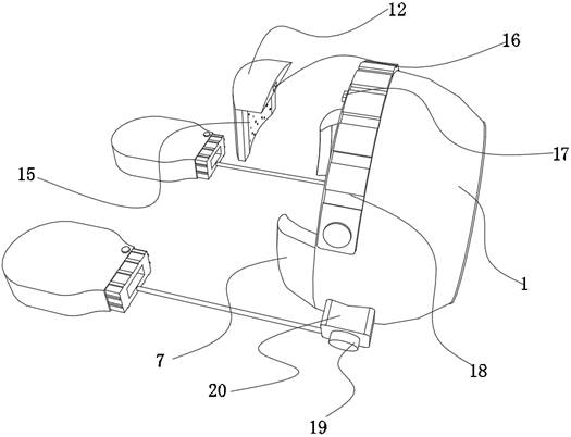
[0039] A pain relief device for migraine sufferers, such as Figure 1-3 As shown, in order to further accelerate the pain relief efficiency; this embodiment makes the following improvements on the basis of Embodiment 1: the outer wall of the cover body 1 is fixed with a winding box 20 by bolts, and the inner wall of the winding box 20 includes a wire roller, The outer wall of the wire roller is wound with a tether rope 23, and one end of the tether rope 23 is welded with an elastic band 6, and one end of the elastic band 6 is welded with a warm glove 8, and the inner wall of the warm glove 8 is wrapped with a water bag, and the inner wall of the water bag is provided with a second The constant temperature heating group and the second constant temperature heating group are respectively electrically connected to the control switch 2 and the control module. The second constant temperature heating group includes a heating rod and a temperature sensor b. The type of the temperature ...


PUM


Abstract

The invention discloses a pain relieving device for migraine patients, and relates to the technical field of neurology nursing instruments. The problem that the relieving treatment effect is poor is solved. The device specifically comprises a cover body, and the outer wall of the cover body is fixedly connected with a control switch; a first pain relieving structure and a second pain relieving structure are arranged on the inner wall of the cover body, the second pain relieving structure comprises a targeted relieving part and an auxiliary massage part, and the targeted relieving part comprises an electric sliding rail, a movable rack, a threaded column and a massage assembly B. The electric sliding rail is fixedly connected to the inner wall of the cover body, the switch control end of the electric sliding rail is electrically connected with the control switch, the movable rack is slidably connected to the inner wall of the electric sliding rail through a sliding block, a gear rotationally connected to the inner wall of the cover body is arranged on the outer wall of the movable rack, and the outer wall of the threaded column is arranged on the inner wall of the gear. According to the invention, the massage is targeted, a better massage effect can be achieved, and the pain of a patient can be effectively relieved.

Description

technical field [0001] The invention relates to the technical field of neurology nursing devices, in particular to a pain relief device for migraine patients. Background technique [0002] Migraine is the most common type of primary headache clinically. The main clinical manifestation is paroxysmal moderate to severe, throbbing headache. The headache is mostly hemilateral and usually lasts for 4 to 72 hours. Headaches can be aggravated by stimuli or everyday activities and relieved by quiet surroundings and rest. In the course of treating migraine in the Department of Neurology, special measures are often required for treatment. Traditional treatments, mostly taking medicine and artificial massage to relieve pain, are time-consuming and laborious and have poor results. [0003] In order to solve the above problems, after retrieval, the Chinese patent application number is CN202022050748.6, which discloses a migraine relief nursing massage device, which includes a housing wi...

Claims


Application Information

Patent Timeline
Patent Type & Authority Applications(China)
IPC IPC(8): A61H7/00A61F7/02A61G7/07A61F9/04A61F11/14
CPCA61H7/007A61F7/02A61F9/045A61F11/14A61G7/072A61H2201/1207A61H2201/1607A61H2205/02A61H2201/10A61F2007/0002A61F2007/0295A61F2007/0054A61F2007/0086A61F2007/0036
Inventor 罗义刘全胜
Owner 罗义
Why Eureka
Try Eureka