Gasket polishing equipment for ocean engineering
A marine engineering and gasket technology, which is applied in metal processing equipment, grinding/polishing equipment, grinding machines, etc., can solve the problems that the grinding angle of large objects cannot be well controlled, the practicability of the device is reduced, and the grinding ability is reduced. To achieve the effect of avoiding irreversibility, prolonging the service life and increasing the limit
- Summary
- Abstract
- Description
- Claims
- Application Information
AI Technical Summary
Problems solved by technology
Method used
Image
Examples
Embodiment 1
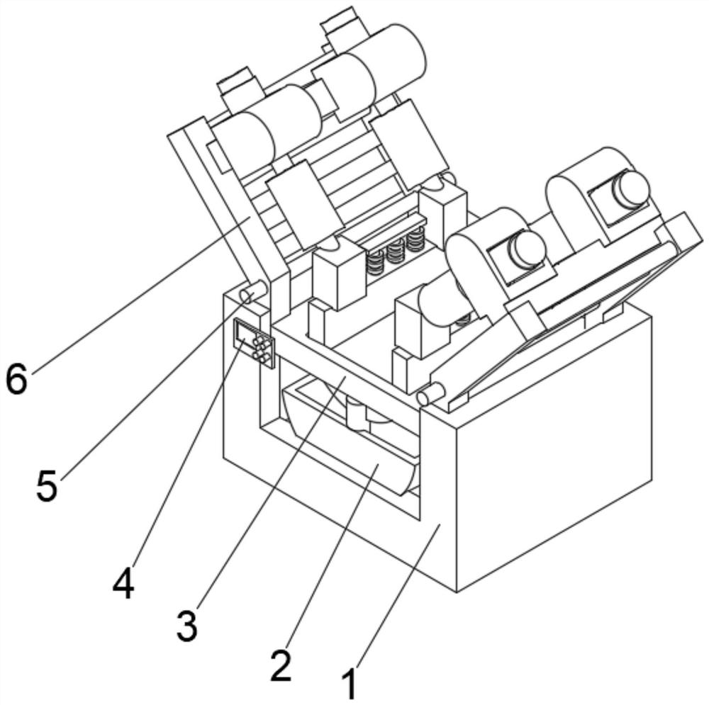
[0032] see Figure 1-2 , the present invention provides a technical solution: a gasket grinding equipment for marine engineering, comprising a main body 1, a driving box 2 is fixedly connected to the bottom of the inner cavity of the main body 1, and a control panel 4 is fixedly connected to the left side of the front top of the main body 1, The top of the inner cavity of the main body 1 is provided with a working platform 3, and the top of the main body 1 is located at the grinding device 6 provided on both sides of the working platform 3. The bottom of the grinding device 6 runs through the main body 1 and extends to the inside of the main body 1. The grinding device 6 Rotary shafts 5 are arranged on both sides of the bottom.
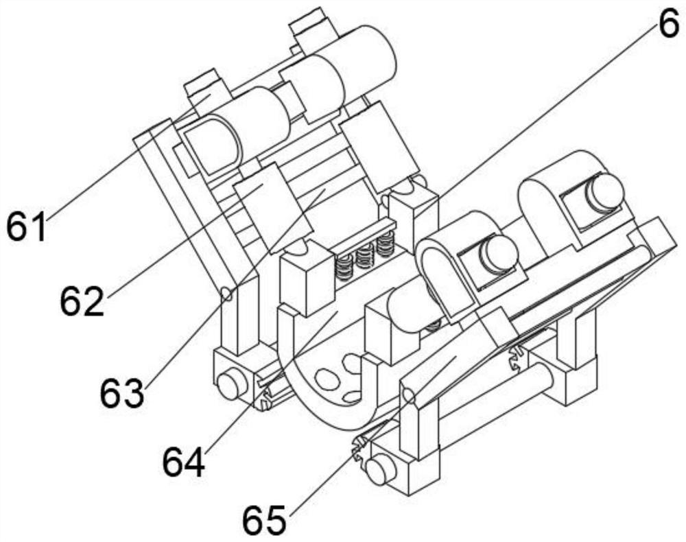
[0033] Wherein, the polishing device 6 includes a fitting mechanism 64, and both sides of the top of the fitting mechanism 64 are provided with a grinding frame 62, and the bottom of the polishing frame 62 runs through the fitting mechanism 64 and ext...
Embodiment 2
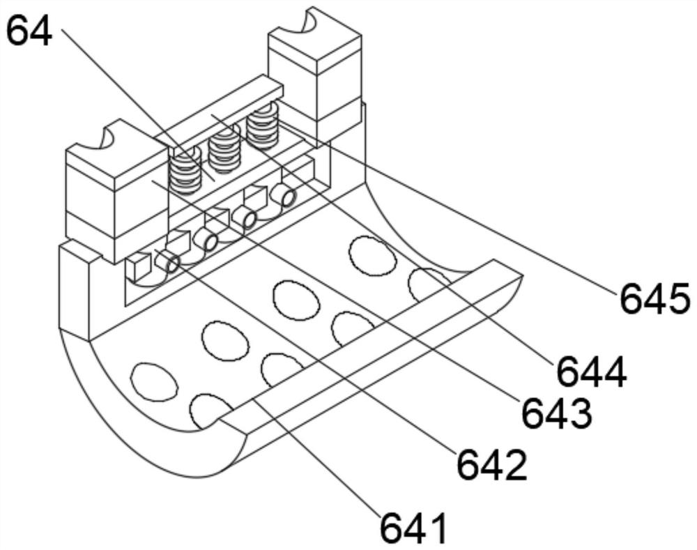
[0036] see Figure 1-4 , on the basis of Embodiment 1, the present invention provides a technical solution: component 1 of the laminating mechanism 64 includes a stabilizing frame 641, an auxiliary supporting frame 644 is fixedly connected to the middle position of the top of the stabilizing frame 641, and the bottom of the auxiliary supporting frame 644 The outer surface is provided with a laminating plate 645 , the top of the stabilizing frame 641 is fixedly connected with fixed connection blocks 643 on both sides of the auxiliary supporting frame 644 , and the top of the inner walls of both sides of the stabilizing frame 641 is provided with suction pieces 642 .
[0037] Wherein, the first component of the adjustment mechanism 65 includes a rotating connector 651, the top two sides of the rotating connector 651 are fixedly connected with a balance adjustment frame 652, and the top right side of the balance adjustment frame 652 is provided with a clamping part 654, and the cl...
Embodiment 3
[0040] see Figure 1-6 , on the basis of Embodiment 1 and Embodiment 2, the present invention provides a technical solution: component 2 of the bonding mechanism 64 includes a bottom plate t1, and a vertical connecting cylinder t4 is provided at the middle of the inner cavity bottom of the bottom plate t1, and the vertical The top of the connecting cylinder t4 penetrates the bottom plate t1 and extends to the outside of the bottom plate t1. The bottom outer surface of the vertical connecting cylinder t4 is provided with a horizontal plate t5. The top of the guide frame t3 is fixedly connected with the adjustment block t2 on both sides.
[0041] Wherein, the second component of the adjustment mechanism 65 includes a protective shell d2, the bottom of the inner cavity of the protective shell d2 is provided with a moving block d1, the outer walls of both sides of the moving block d1 penetrate the protective shell d2 and extend to the outside of the protective shell d2, the protec...
PUM
 Abstract
Description
Claims
Application Information
 - R&D
- Intellectual Property
- Life Sciences
- Materials
- Tech Scout
- Unparalleled Data Quality
- Higher Quality Content
- 60% Fewer Hallucinations
Browse by: Latest US Patents, China's latest patents, Technical Efficacy Thesaurus, Application Domain, Technology Topic, Popular Technical Reports.
© 2025 PatSnap. All rights reserved.Legal|Privacy policy|Modern Slavery Act Transparency Statement|Sitemap|About US| Contact US: help@patsnap.com


