Backlight assembly attaching method and equipment

A technology for backlight components and laminating equipment, which is applied in chemical instruments and methods, optics, nonlinear optics, etc., to achieve the effect of saving labor costs, reducing technological processes, and reducing bad scratches

Pending Publication Date: 2021-12-14
XIAMEN YIJINLU TECH CO LTD
View PDF7 Cites 2 Cited by
  • Summary
  • Abstract
  • Description
  • Claims
  • Application Information

AI Technical Summary

Problems solved by technology
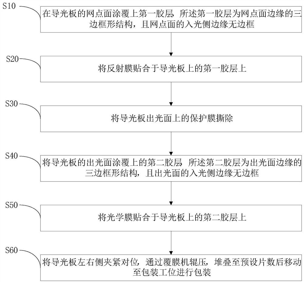
[0003] Based on this, it is necessary to provide a backlight assembly bonding method and equipment for the above problems

Method used


Image

  • Backlight assembly attaching method and equipment
  • Backlight assembly attaching method and equipment
  • Backlight assembly attaching method and equipment

Examples


Embodiment Construction

[0030] In order to make the above objects, features and advantages of the present invention more obvious and comprehensible, specific embodiments of the present invention will be clearly and completely described below in conjunction with the accompanying drawings. Apparently, the specific details described below are only some embodiments of the present invention, and the present invention can also be implemented in many other embodiments different from those described here. Based on the embodiments of the present invention, all other embodiments obtained by persons of ordinary skill in the art without making creative efforts belong to the protection scope of the present invention.

[0031] It should be noted that when an element is referred to as being “fixed” to another element, it can be directly on the other element or there can also be an intervening element. When an element is referred to as being "connected to" another element, it can be directly connected to the other e...


PUM

PropertyMeasurementUnit
widthaaaaaaaaaa
thicknessaaaaaaaaaa

Abstract

The invention relates to a backlight assembly attaching method and equipment, and the method comprises the steps: coating a lattice point surface of a light guide plate with a first adhesive layer , wherein the first adhesive layer is of a three-frame-shaped structure at the edge of the lattice point surface, and the edge of the light incident side of the lattice point surface is free of a frame; attaching a reflecting film to the first adhesive layer on the light guide plate; coating the light-emitting surface of the light guide plate with the second adhesive layer, wherein the second adhesive layer is of a three-frame-shaped structure of the edge of the light-emitting surface, and the edge of the light-entering side of the light-emitting surface is free of a frame; and attaching the optical film to the second adhesive layer on the light guide plate. The reflecting layer, the light guide plate and the optical film layer are fixed to form an integrated structure, the optical performance of the integrated structure cannot be affected, the integrated structure can be directly installed in a complete machine factory, the reflecting layer, the light guide plate and the optical film layer do not need to be assembled again, the technological process is reduced for the complete machine factory, the assembly efficiency is improved, the labor cost is saved, and the assembly reject ratio is reduced; and a protection film does not need to be covered for protection, so that the light blocking phenomenon caused by the refractive index of the adhesive layer can be effectively avoided.

Description

technical field [0001] The invention relates to the technical field of backlight modules, in particular to a bonding method and equipment for backlight components. Background technique [0002] With the increasing popularity of liquid crystal products, users are becoming more and more picky about the products, and put forward higher and higher requirements for the quality of the products. The general structure remains unchanged, and the performance cannot be reduced. The overall structural design of the existing backlight module has been difficult to meet the increasingly stringent user needs. In the existing technology, the assembly process of the backlight module is in the complete machine factory, which separates the backplane, reflective layer, and light guide plate. , light-enhancing film, and diffusion film are stacked together in turn and then covered with a plastic frame to form a backlight module. The existing structure of multiple film sheets and light guide plate...

Claims


Application Information

Patent Timeline
Patent Type & Authority Applications(China)
IPC IPC(8): B32B37/12B32B37/10B32B38/10B32B38/00B32B41/00G02F1/1333
CPCB32B37/1292B32B37/10B32B38/10B32B38/00B32B41/00G02F1/1333B32B2038/0076
Inventor 黄清海黄耀鹭汤璐欣
Owner XIAMEN YIJINLU TECH CO LTD
Why Eureka
Try Eureka