Composite light guide plate structure and backlight module

A light guide plate and combined technology, applied in the field of light guide plates, can solve problems such as inconvenient manufacture and installation, light blocking of light guide plates, easy to cause dirt, etc., to achieve the effects of improving assembly efficiency, reducing process flow, and reducing assembly failure rate

Pending Publication Date: 2021-09-28
XIAMEN YIJINLU TECH CO LTD
View PDF0 Cites 0 Cited by
  • Summary
  • Abstract
  • Description
  • Claims
  • Application Information

AI Technical Summary

Problems solved by technology

The overall structural design of the existing backlight module has been difficult to meet the increasingly stringent user needs. In the existing technology, the assembly process of the backlight module is in the complete machine factory, which separates the backplane, reflective layer, and light guide plate. , light-enhancing film, and diffusion film are stacked together in turn and then covered with a plastic frame to form a backlight module. The existing structure of multiple film sheets and light guide plates is very inconvenient to manufacture and install, and the process is cumbersome and easy to cause dirty If the light guide plate can be fixedly connected with the reflective layer, light-enhancing film, diffusion film, etc. to form a whole before the light guide plate leaves the factory, the above problems can be well solved
However, if the reflective layer, light guide plate, light-enhancing film, and diffusion film are pasted and fixed in sequence by using the entire adhesive layer, due to the problem of the refractive index of the adhesive layer, the light guide plate has a phenomenon of light blocking where the light is concentrated on the light incident side, which cannot meet the requirements. , there is no composite light guide plate on the market that fixes the reflective layer, light guide plate, enhancement film, diffusion film, etc.

Method used


Image

  • Composite light guide plate structure and backlight module
  • Composite light guide plate structure and backlight module
  • Composite light guide plate structure and backlight module

Examples


Embodiment 1

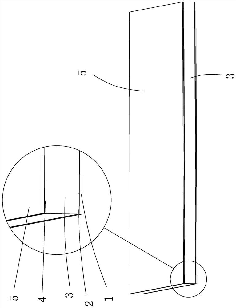
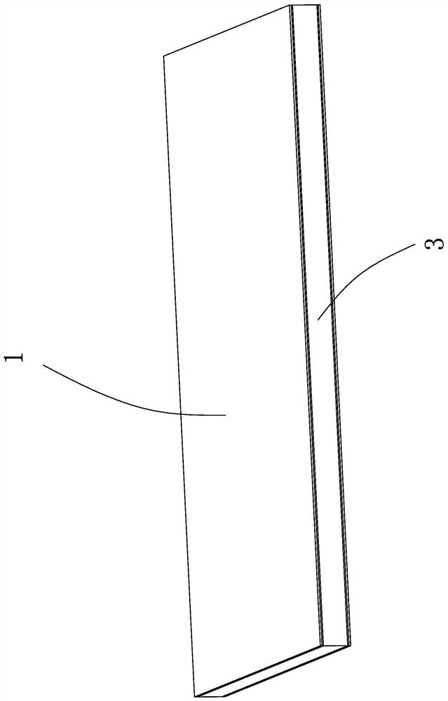
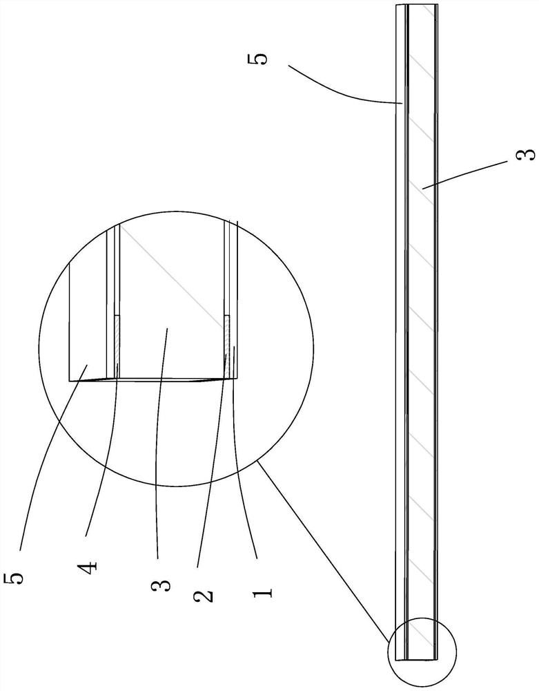
[0028] Such as Figure 1-4 As shown, a composite light guide plate structure, including from bottom to top (with figure 1 The reflective layer 1, the first adhesive layer 2, the light guide plate 3, the second adhesive layer 4 and the optical film layer 5 are arranged in sequence, the dots of the light guide plate 3 are arranged facing downwards, and the light-emitting surface is arranged facing upwards, and the light guide plate 3. The light incident surface is on the side. In this specific embodiment, the light guide plate 3 has a rectangular structure, but it is not limited thereto. In some embodiments, the shape of the light guide plate 3 can be set according to actual needs.

[0029] The light guide plate 3 can adopt various existing light guide plate structures, such as flat plates, wedge-shaped plates, etc., can be formed by injection molding, cutting molding, etc., and can be made of materials such as acrylic plates and PC (polycarbonate) plates. become.

[0030] Bo...

Embodiment 2

[0040] Such as Figure 6-8 As shown, the difference between this specific embodiment and Embodiment 1 is that: the optical film layer 5 of this specific embodiment is a composite film layer, and each film layer of the composite film layer is bonded and fixed by frame-shaped adhesive layers in sequence, and the adhesive layers are respectively It is arranged between the edges of each film layer, and the composite film layer is used to improve the brightening effect, and the structure is easy to realize and low in cost.

[0041] Specifically, in this embodiment, the composite film layer 5 includes a first brightness enhancement film 51, a third adhesive layer 52, a second brightness enhancement film 53, a fourth adhesive layer 54 and a diffusion layer 55, the third adhesive layer 52 and the second adhesive layer The four adhesive layers 54 are all rectangular frame structures, and the second adhesive layer 4 is arranged between the edge of the light-emitting surface of the light...


PUM

PropertyMeasurementUnit
thicknessaaaaaaaaaa
widthaaaaaaaaaa

Abstract

The invention relates to the field of light guide plates. The invention discloses a composite light guide plate structure and a backlight module. The composite light guide plate structure comprises a reflecting layer, a first adhesive layer, a light guide plate, a second adhesive layer and an optical film layer which are sequentially arranged from bottom to top, the lattice point face of the light guide plate is arranged downwards, the light emitting face of the light guide plate is arranged upwards, and the first adhesive layer and the second adhesive layer are each of a frame-shaped structure. The first adhesive layer is arranged between the edge of the upper surface of the reflecting layer and the edge of the lattice point surface of the light guide plate to fixedly bond the reflecting layer and the light guide plate together, and the second adhesive layer is arranged between the edge of the light emitting surface of the light guide plate and the edge of the lower surface of the optical film layer to fixedly bond the optical film layer and the light guide plate together. The reflecting layer, the light guide plate and the optical film layer are fixed to form an integrated structure without affecting the optical performance of the integrated structure, the technological process is reduced for a whole machine factory, the assembly efficiency is improved, the labor cost is saved, and the assembly reject ratio is reduced; and the protection effect on the light guide plate is better.

Description

technical field [0001] The invention belongs to the field of light guide plates, and in particular relates to a composite light guide plate structure and a backlight module. Background technique [0002] With the increasing popularity of liquid crystal products, users are becoming more and more picky about the products, and put forward higher and higher requirements for the quality of the products. The general structure remains unchanged, and the performance cannot be reduced. The overall structural design of the existing backlight module has been difficult to meet the increasingly stringent user needs. In the existing technology, the assembly process of the backlight module is in the complete machine factory, which separates the backplane, reflective layer, and light guide plate. , light-enhancing film, and diffusion film are stacked together in turn and then covered with a plastic frame to form a backlight module. The existing structure of multiple film sheets and light g...

Claims


Application Information

Patent Timeline
Patent Type & Authority Applications(China)
IPC IPC(8): G02B6/00
CPCG02B6/004G02B6/0055G02B6/0051G02B6/0088
Inventor 黄清海黄耀鹭汤璐欣
Owner XIAMEN YIJINLU TECH CO LTD
Why Eureka
Try Eureka