Heat recovery unit and control method thereof

A technology for recovering units and control methods, applied in the field of air conditioners, can solve the problem of not guaranteeing the stable operation of units, and achieve the effects of stable cooling effect, timely feedback, and good control effect.

Inactive Publication Date: 2021-12-14
GREE ELECTRIC APPLIANCES INC OF ZHUHAI
View PDF5 Cites 0 Cited by
  • Summary
  • Abstract
  • Description
  • Claims
  • Application Information

AI Technical Summary

Problems solved by technology

[0003] The present invention proposes a heat recovery unit and its control method to solve the problem in the prior art that the heat demand change on the user side of waste heat recovery cannot guarantee the stable operation of the unit

Method used


Image

  • Heat recovery unit and control method thereof
  • Heat recovery unit and control method thereof
  • Heat recovery unit and control method thereof

Examples


Embodiment Construction

[0021] In order to make the object, technical solution and advantages of the present invention clearer, the present invention will be described in detail below in conjunction with the accompanying drawings and embodiments. It should be understood that the following specific examples are only used to explain the present invention, but not to limit the present invention.

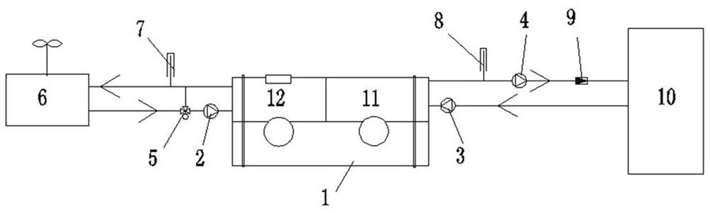
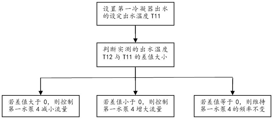
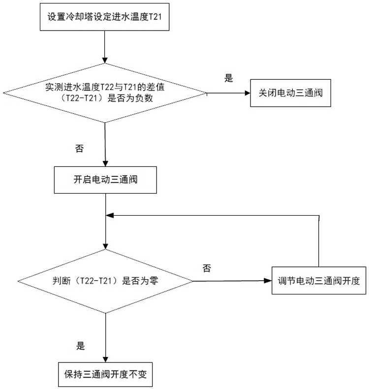
[0022] In the present invention, two condensers in series are arranged on the condensation side of the unit, one of which provides hot water for the user side, and after the hot water supply of the user side is satisfied, the remaining heat is taken away by the cooling water of the other condenser. The cooling water from the outlet is circulated after passing through the cooling tower to dissipate heat. At the same time, the controller is used to control the inlet water temperature of the cooling tower to ensure the stable operation of the unit when the water load on the user side changes.

[0023] The heat r...


PUM


Abstract

The invention discloses a heat recovery unit and a control method thereof. The heat recovery unit comprises a first condenser and a second condenser which are connected in series, the first condenser is connected with a user side hot water system, the second condenser is connected with a cooling water system, the heat recovery unit further comprises a first controller used for controlling the water outlet flow according to the user side temperature requirement, and a second controller used for controlling the water inlet temperature of a cooling tower. On the basis that the condenser is used for heat dissipation, the good operation state of the unit is maintained, waste heat is effectively utilized, and energy conservation, emission reduction and carbon emission reduction are really achieved.

Description

technical field [0001] The invention relates to the technical field of air conditioning, in particular to a heat recovery unit and a control method thereof. Background technique [0002] With the formulation of the country's carbon reduction and energy saving goals, the concept of energy saving and high efficiency has attracted more and more attention from all walks of life. For the air conditioning industry, the reuse of waste heat is a powerful measure of energy saving. In the heat recovery air conditioning unit, the heat released by the condenser is usually discharged to the surroundings by cooling towers or cooling fans. This method is actually a huge waste of energy, and at the same time brings certain waste heat pollution to the surrounding environment. For archives, clean rooms and other places that require high indoor temperature and humidity, a constant temperature and humidity heat recovery air conditioning unit is generally used. The waste heat discharged from th...

Claims


Application Information

Patent Timeline
IPC IPC(8): F24F5/00F24F12/00F24F13/30F24F11/89F24F11/63F24F11/70F24F11/64
CPCF24F5/0096F24F12/00F24F13/30F24F11/89F24F11/63F24F11/70F24F11/64F24F2221/183Y02B30/56
Inventor 李宏波韦韬孙康石永静董蓉
Owner GREE ELECTRIC APPLIANCES INC OF ZHUHAI
Why Eureka
Try Eureka