
Turbine rotor locking plate assembling device and using method thereof

A technology for assembling devices and turbine rotors, which is applied in the direction of feeding devices, positioning devices, storage devices, etc., can solve the problems of blade bumping and blade 10 falling at the same time, so as to ensure the installation quality, improve the installation efficiency, and satisfy the flatness Effect

Pending Publication Date: 2021-12-17
CHINA HANGFA SOUTH IND CO LTD
View PDF7 Cites 1 Cited by
  • Summary
  • Abstract
  • Description
  • Claims
  • Application Information

AI Technical Summary

Problems solved by technology

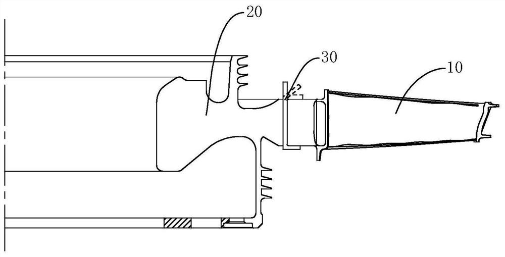
Since the angle of inclination between the tenon and the tenon of this type of structure is 0°, that is, the direction of the tenon and the axial direction of the turbine disk 20 are collinear, at this time the blade 10 will fall from the tenon groove of the turbine disk 20 onto the work surface. There is a certain gap in the locking piece 30 in the tongue and groove, so it is easy for multiple blades 10 to fall at the same time, causing the blades to collide.

Method used


Image

  • Turbine rotor locking plate assembling device and using method thereof
  • Turbine rotor locking plate assembling device and using method thereof
  • Turbine rotor locking plate assembling device and using method thereof

Examples


Embodiment Construction

[0026] The embodiments of the present invention will be described in detail below with reference to the accompanying drawings, but the present invention can be implemented in various ways defined and covered below.

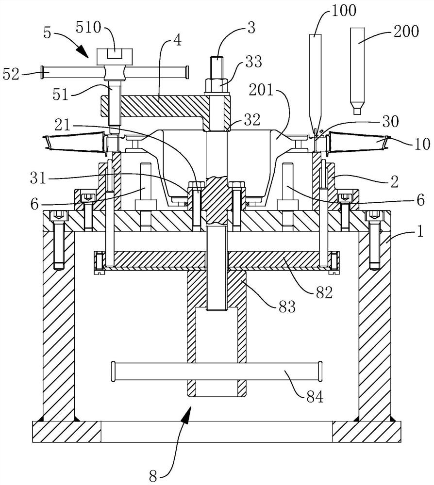
[0027] like image 3 As shown, the embodiment of the present invention provides a turbine rotor locking piece assembly device, which is used for assembling the blade 10 and the locking piece 30 on the turbine disk 20 . The turbine disk 20 is divided into a first-stage turbine disk 201 and a second-stage turbine disk 202 . The turbine rotor locking plate assembly device includes a base 1 , a support 2 , a pull rod 3 , a rotating arm 4 and a pressing assembly 5 . The support 2 is fixed on the base 1 , and the top surface of the support 2 is used to support the lower bent portion of each locking piece 30 on the first-stage turbine disk 201 . The pull rod 3 is vertically fixed on the horizontal support portion of the base 1 and arranged coaxially with the support 2....


PUM


Abstract

The invention discloses a turbine rotor locking plate assembling device and a using method thereof. The turbine rotor locking plate assembling device comprises a base, a support, a pull rod, a rotating arm and a pressing assembly. The support is fixed to the base, the pull rod is vertically fixed to a horizontal supporting part of the base and is coaxially with the support, a positioning barrel is arranged at the position, located above the horizontal supporting part of the base, of the pull rod, one end of the rotating arm is rotatably installed on the pull rod and arranged above the positioning barrel in a spaced mode, and the pressing assembly is arranged at the other end of the rotating arm so as to execute downward pressing action. According to the turbine rotor locking plate assembling device, A locking plate can be conveniently and reliably mounted, the mounting quality is guaranteed, and the mounting efficiency is improved.

Description

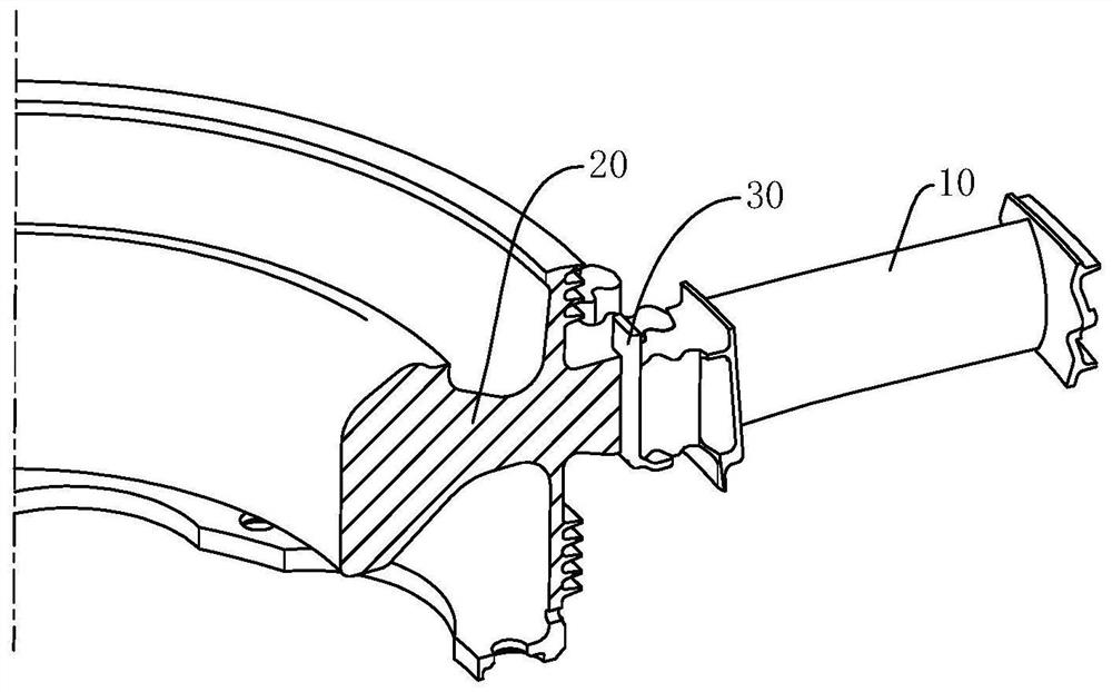
technical field [0001] The invention relates to the technical field of aero-engine assembly, in particular to a turbine rotor lock plate assembly device and a method for using the same. Background technique [0002] like figure 1 and figure 2 As shown, the blade 10 of the aero-engine is installed into the turbine disk 20 through a tongue and groove, and the locking piece 30 needs to be bent by 90°, so as to maintain the assembly relationship between the turbine disk 20 and the blade 10 . After the locking piece 30 is assembled, it is necessary to ensure that the flatness between the tenon end surface of the blade 10 and the end surface of the turbine disk 20 is within a certain range. However, the existing installation method is cumbersome to operate, the installation efficiency is low, and it is difficult to guarantee the installation quality. [0003] When decomposing the locking piece 30 , it is necessary to use a professional tool to pry the locking piece 30 open. A...

Claims


Application Information

Patent Timeline
IPC IPC(8): B21D39/00B21D43/00B21D53/78B25B11/00
CPCB21D39/00B21D43/003B21D53/78B25B11/00Y02E10/20
Inventor 高航黄晓鸣赵媛媛王鹏杨世春张敏
Owner CHINA HANGFA SOUTH IND CO LTD
Learn More