Printer internal ink conveying pipe auxiliary device with automatic heating and anti-blocking functions

A technology of automatic heating and auxiliary devices, which is applied in the direction of mixers, printing and mixers with rotating stirring devices, which can solve the problems of no anti-blocking devices, lack of automatic heating devices for ink delivery tubes, etc., and achieve the effect of avoiding flow speed

Inactive Publication Date: 2021-12-17
厦门各速贸易有限公司
View PDF0 Cites 0 Cited by
  • Summary
  • Abstract
  • Description
  • Claims
  • Application Information

AI Technical Summary

Problems solved by technology

[0005] Aiming at the deficiencies of the prior art, the present invention provides an automatic heating and anti-clogging auxiliary device for the ink delivery tube inside the printer, which has the advantages of an automatic heating device and an anti-blocking device, and solves the problem of lack of an automatic heating device for the existing ink delivery tube. The problem of no anti-blocking device

Method used


Image

  • Printer internal ink conveying pipe auxiliary device with automatic heating and anti-blocking functions
  • Printer internal ink conveying pipe auxiliary device with automatic heating and anti-blocking functions
  • Printer internal ink conveying pipe auxiliary device with automatic heating and anti-blocking functions

Examples


Embodiment 1

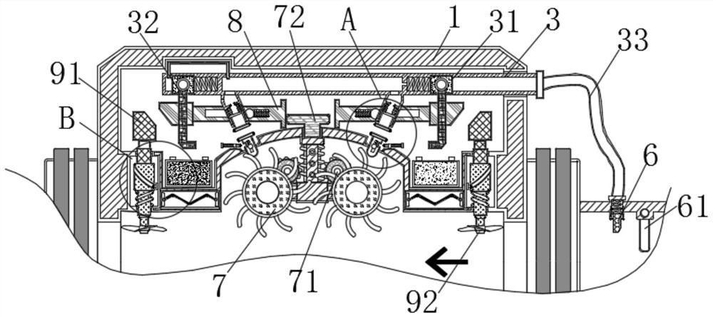
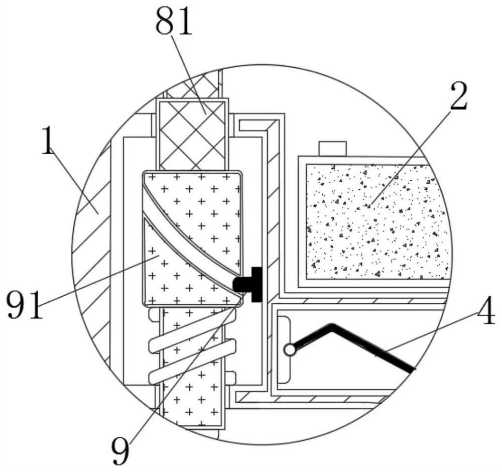
[0024] see Figure 1-2 , an automatic heating and anti-blocking auxiliary device for ink delivery tubes inside the printer, including a casing 1 and a power supply 2, a support mechanism 3 is fixedly connected to the upper part of the casing 1, and a slider 31 is slidably connected to the inside of the support mechanism 3. The slider 31 A fixed rod 32 is fixedly connected to the surface, an air pipe 33 is fixedly connected to the right side of the support mechanism 3 , and a heating mechanism 4 is arranged at the bottom of the power supply 2 .

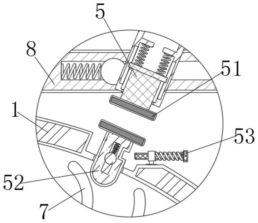
[0025] Further, the end of the fixed rod 32 away from the inner wall of the casing 1 is provided with a first push block 5, the bottom end of the first push block 5 is fixedly connected with a contact 51, and the bottom of the contact 51 is provided with a second push block 52, the second push block 5 A notch is provided on the surface of the block 52, and the second push block 52 is provided with a blocking rod 53 near one end of the ...

Embodiment 2

[0029] see Figure 3-4 , an automatic heating and anti-blocking auxiliary device for ink delivery tubes inside the printer, including a casing 1 and a power supply 2, a support mechanism 3 is fixedly connected to the upper part of the casing 1, and a slider 31 is slidably connected to the inside of the support mechanism 3. The slider 31 A fixed rod 32 is fixedly connected to the surface, an air pipe 33 is fixedly connected to the right side of the support mechanism 3 , and a heating mechanism 4 is arranged at the bottom of the power supply 2 .

[0030] Further, the bottom of the second push block 52 is provided with a roller 7, and the back of the roller 7 is provided with a runner 71, and the tooth grooves on the surface of the runner 71 match the tooth grooves on the back of the roller 7, and the runner 71 is arranged at an end far away from the roller 7. There is a movable rod 72, the ink drives the roller 7 to rotate, so that the roller 7 drives the runner 71 to rotate thr...


PUM


Abstract

The invention discloses a printer internal ink conveying pipe auxiliary device with automatic heating and anti-blocking functions. The printer internal ink conveying pipe auxiliary devicecomprises a machine shell and a power source, wherein a supporting mechanism is fixedly connected to the upper portion of the machine shell; a sliding block is slidably connected to the inside of the supporting mechanism; a fixing rod is fixedly connected to the surface of the sliding block; an air pipe is fixedly connected to the right side of the supporting mechanism; and a heating mechanism is arranged at the bottom of the power source. According to the printer internal ink conveying pipe auxiliary device with the automatic heating and anti-blocking functions, the sliding block drives a first push block to slide by extruding air, so that the first push block drives a contact to make contact with a contact on the surface of a second push block, the situation that a heating mechanism is automatically opened when ink is not fed is prevented, meanwhile, a fixing rod extrudes a blocking rod to slide rightwards and enables the blocking rod to be clamped in a notch, and the position of a second push block in the machine shell is fixed; and when the contacts on the two sides make contact with each other, the power source is turned on through an external circuit, the heating mechanism starts to dissipate heat, and the effect of automatically heating an ink conveying pipe is achieved.

Description

technical field [0001] The invention relates to the technical field of ink delivery tubes of printers, in particular to an automatic heating and anti-blocking auxiliary device for ink delivery tubes inside a printer. Background technique [0002] With the continuous development of social and economic conditions, printers have been widely used in daily office, education or medical equipment and other fields. Printers are one of the output devices of computers, which print the processing results in computers on related media. Various types have been derived under the changes of the times, including inkjet printers. [0003] The ink supply tube is an indispensable part inside the inkjet printer, but the current ink supply tube generally lacks an automatic heating device. When the outside temperature is too low, the ink will become viscous in the ink supply tube, or even condense into a solid, thus affecting The flow speed of the ink in the ink delivery tube requires an anti-bl...

Claims


Application Information

Patent Timeline
Patent Type & Authority Applications(China)
IPC IPC(8): B41J2/175B41J2/17B01F7/00B01F7/18
CPCB41J2/175B41J2/17
Inventor 张纪昕
Owner 厦门各速贸易有限公司
Why Eureka
Try Eureka