Oilless air compressor with circulating cooling function

An oil-free air compressor and circulating cooling technology, which is applied to the control mechanism of the wing fan, mechanical equipment, power control mechanism, etc., can solve the problems of limited heat dissipation and easy damage of the cooling fan

Pending Publication Date: 2021-12-17
南城拓玛仕机电科技有限公司
View PDF6 Cites 1 Cited by
  • Summary
  • Abstract
  • Description
  • Claims
  • Application Information

AI Technical Summary

Problems solved by technology

[0004] In order to overcome the disadvantages that the air compressor is easily damaged at high temperature and the heat dissipation function of the cooling fan of the equipment itself is limited, the technical problem of the present invention is to provide a belt that can effectively cool down the air compressor and avoid high temperature damage to the air compressor. Oil-free air compressor with circulating cooling function

Method used


Image

  • Oilless air compressor with circulating cooling function
  • Oilless air compressor with circulating cooling function
  • Oilless air compressor with circulating cooling function

Examples


Embodiment 1

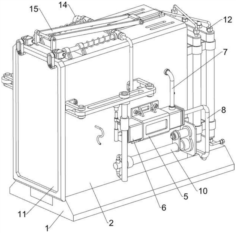
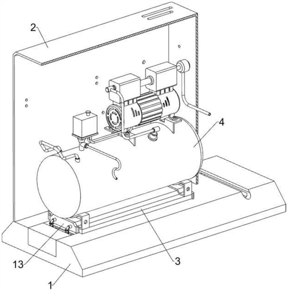
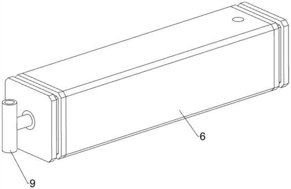
[0035] An oil-free air compressor with circulating cooling function, such as Figure 1-7 As shown, it includes a base 1, a housing 2, a guide block 3, an air compressor 4, a fixed frame 5, a cylinder body 6, an air outlet pipe 7, an air suction pipe 8, a piston rod 9, a push assembly 10 and a cover assembly 11, There is a groove on the left side of the base 1, a housing 2 is provided on the top of the base 1, four through holes are opened on the right side of the top of the housing 2, and the through holes are used for heat dissipation, and a guide block 3 is welded on the left side of the top of the base 1, and the guide block 3 is located in the housing 2, and the air compressor 4 is slidingly installed on the guide block 3, and the lower and right sides of the front and rear sides of the housing 2 are fixed with a fixed frame 5 by bolts, and a cylinder body 6 is set inside the fixed frame 5 , the air outlet pipe 7 is connected between the right side of the top of the cylind...

Embodiment 2

[0042] On the basis of Example 1, such as figure 1 , figure 2 , Figure 4 , Figure 8 , Figure 9 , Figure 10 , Figure 11 , Figure 12 , Figure 13 , Figure 14 and Figure 15 As shown, cooling assembly 12 is also included, and cooling assembly 12 can produce cold air. Vent pipe 128, the upper and lower sides on the right side of housing 2 are all connected with support plates 121 by bolts, two processing frames 122 are arranged between the upper and lower support plates 121, and the suction pipe 8 is connected with the processing frame 122 of the inner side. The bottom is connected, and the front and rear sides of the outer processing frame 122 are provided with air intake pipes 123, and the processing frame 122 is provided with cooling pipes 124, which are used to make cold air, and the outer processing frame 122 is provided with water inlet pipes at the bottom and front side 125, the water inlet pipe 125 is connected to the cooling pipe 124 on the outside, the ...


PUM


Abstract

The invention relates to an oilless air compressor, in particular to an oilless air compressor with a circulating cooling function. According to the oilless air compressor with the circulating cooling function, the air compressor can be effectively cooled, and the air compressor is prevented from being damaged by high temperature. The oilless air compressor with the circulating cooling function comprises a base, a shell, a guide block, an air compressor body, fixing frames and the like, a groove is formed in the left side of the base, the shell is arranged at the top of the base, the guide block is arranged on the left side of the top of the base and located in the shell, the air compressor body is arranged on the guide block in a sliding mode, and the fixing frames are arranged on the right sides of the lower portions of the front side and the rear side of the shell. A piston rod slides left and right to continuously suck outside air into the shell, hot air in the shell is discharged through a through hole, air circulation in the shell is accelerated through left-right sliding of the piston rod, and the purpose of cooling the interior of the shell is achieved.

Description

technical field [0001] The invention relates to an oil-free air compressor, in particular to an oil-free air compressor with a circulating cooling function. Background technique [0002] Oil-free air compressor refers to oil-free air compressor, air compressor is a common air pressure generating device. The main function of the air compressor is to provide the required gas. The more common uses are as air power, for bottling or pipeline gas transportation. During the long-term and continuous operation of the air compressor, the air compressor itself will generate heat, which will cause the temperature of the surrounding air to rise. If the air compressor is in operation, the temperature of the surrounding air will be too high, which will damage the internal structure of the air compressor. Such as the machine head is seized, the temperature control valve fails to work, the host of the air compressor is damaged, and the service life of the equipment is shortened. However, t...

Claims


Application Information

Patent Timeline
Patent Type & Authority Applications(China)
IPC IPC(8): F04B39/06F04B39/12E05F15/60
CPCF04B39/06F04B39/066F04B39/121E05F15/60
Inventor 谭运杰冯卿华
Owner 南城拓玛仕机电科技有限公司
Why Eureka
Try Eureka