Wear-resistant sealing structure of servo hydraulic cylinder

A servo hydraulic cylinder and sealing structure technology, applied in the field of hydraulic cylinders, can solve the problems of the protection structure and method without the wear-resistant sealing effect of the piston position, and the reduction of the sealing effect of the piston-piston position, etc. Wear-resistant use effect, improve the effect of sealing effect

Pending Publication Date: 2021-12-17
郑文斌
View PDF0 Cites 0 Cited by
  • Summary
  • Abstract
  • Description
  • Claims
  • Application Information

AI Technical Summary

Problems solved by technology

[0003] In the process of using the hydraulic cylinder in the prior art, the rod body and the piston often reciprocate for a long time, and the piston is greatly worn and the sealing effect of the piston position is reduced. However, the prior art only pays attention to the sealing of the opening position of the cylinder body For the protection effect, the piston position is only considered to use wear-resistant materials for the piston, but there is no protection structure and method for the wear-resistant sealing effect of the piston position

Method used


Image

  • Wear-resistant sealing structure of servo hydraulic cylinder
  • Wear-resistant sealing structure of servo hydraulic cylinder
  • Wear-resistant sealing structure of servo hydraulic cylinder

Examples


Embodiment 1

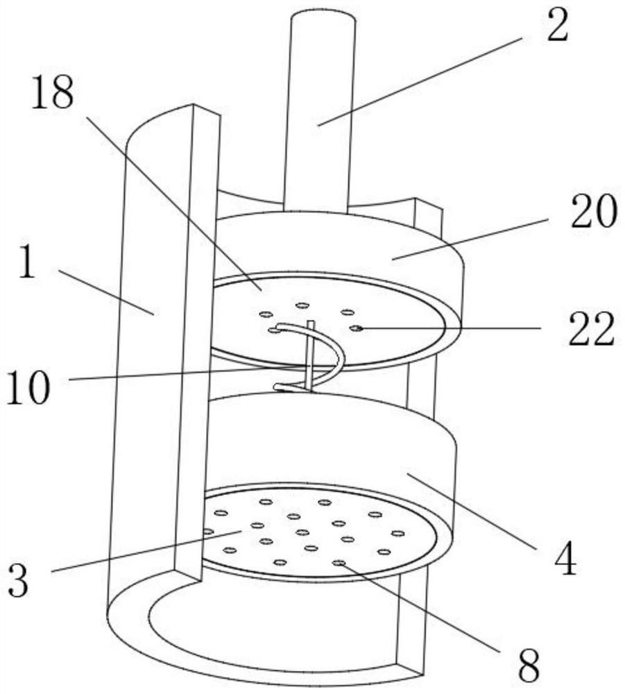
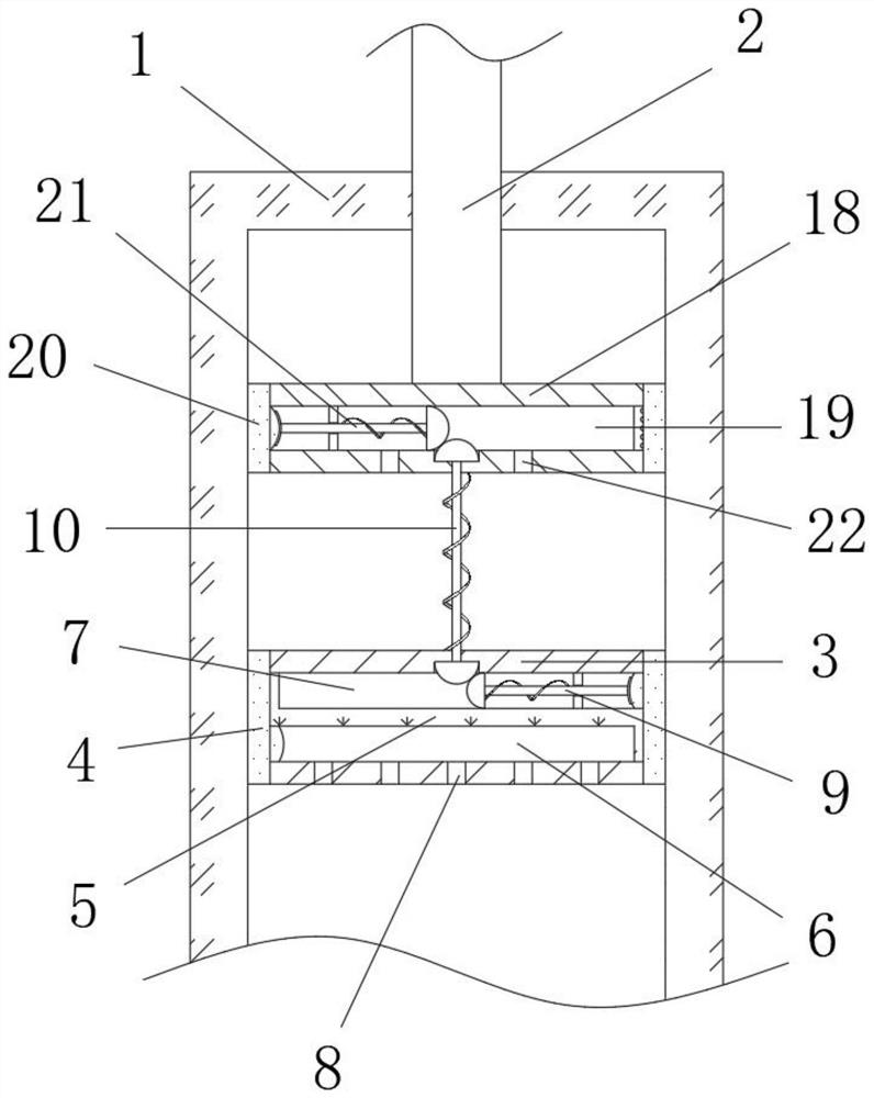
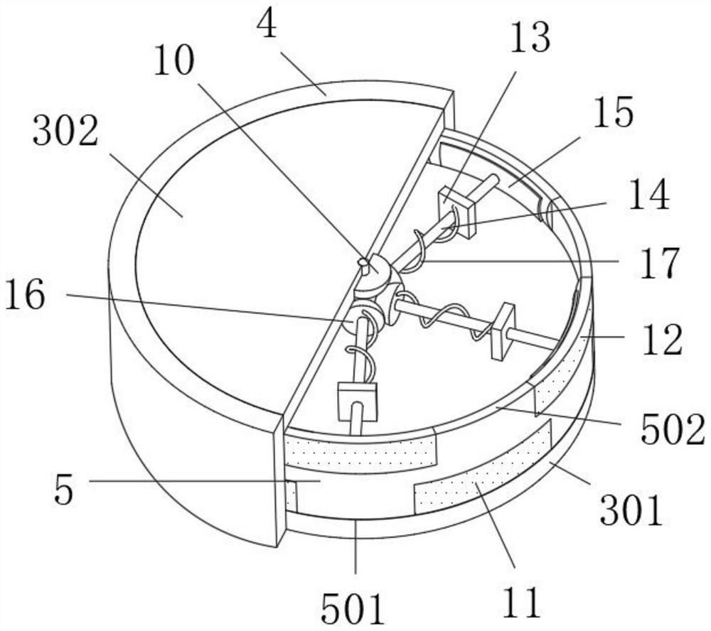
[0028] Refer Figure 1 - Figure 4A servo hydraulic cylinder wear-resistant sealing structure, including the cylinder 1 and the telescopic rod 2, and the bottom end of the telescoping rod 2 is fixedly connected to the inner wall of the cylinder 1, and the outer wall sleeve of the piston member 3 is fixed. The first rubber sleeve 4 of the case is provided with a hydraulic chamber 6 in the bottom of the piston member 3, and the bottom of the hydraulic chamber 6 is in communication with the bottom of the cylinder 1, and the liquid is injected into the liquid and the pressing of the piston member 3 is telescopically. The liquid and the air pressure will enter the hydraulic chamber 6 and extruded the bottom of the inner wall of the first rubber sleeve 4, and the top portion of the piston member 3 is provided with an extruded chamber 7, and the position corresponding to the first rubber sleeve 4 is provided in the extruder 7. Mechanical buffer structure, the piston frame 3 is extruded dur...

Embodiment 2

[0033] Example 2 includes all structures and methods of Example 1, reference Figure 1 - Figure 6 A servo hydraulic cylinder wear-resistant sealing structure, further comprising, the bottom end of the telescoping rod 2 fixes a fixing member 18, and the outer wall of the fixing member 18 has a second rubber sleeve 20 of the annular structure, the bottom of the fixture 18 A connecting buffer mechanism 10 is connected between the intermediate position of the piston member 3, and the inside of the fixing member 18 is opened, and a plurality of horizontal placed second extrudation mechanisms 21, the second extrusion 19 are provided in the connection chamber 19. The mechanism 21 is adapted to the connection buffer mechanism 10, and the second extrusion mechanism 21 and the first extrusion mechanism 9 are arranged to be spaced apart from the circumferential surface, thereby constituting a fixed plug and a moving plug through the fixing member 18 and the piston member 3. To achieve the buf...


PUM


Abstract

The invention belongs to the technical field of hydraulic cylinders, in particular to a wear-resistant sealing structure of a servo hydraulic cylinder. The following solution is provided, the wear-resistant sealing structure comprises a cylinder block and a telescopic rod, wherein a piston part slidably connected to the inner wall of the cylinder block is fixed to the bottom end of the telescopic rod, a first rubber sleeve of an annular structure fixedly sleeves the outer wall of the piston part, a hydraulic cavity is formed in the bottom in the piston piece, the bottom of the hydraulic cavity communicates with the bottom of the cylinder block, and when liquid is injected into the cylinder block to extrude the piston piece to stretch out and draw back, and the liquid and air pressure can enter the hydraulic cavity to extrude the bottom of the inner wall of the first rubber sleeve. According to the wear-resistant sealing structure, the sealing effect of the actual piston position is improved through outward inclined extrusion of the first rubber sleeve, and the first rubber sleeve is extruded outwards through inclined conversion of the bottom and the top in cooperation with hydraulic pressure and machinery, so that the effectiveness and the wear-resisting effect of the piston piece in long-term use are improved, and the wear-resisting and sealing effects of the hydraulic cylinder are greatly improved through cooperation of the hydraulic extrusion and the mechanical extrusion.

Description

Technical field [0001] The present invention relates to the field of hydraulic cylinders, more particularly to a servo cylinder abradable seal structure. Background technique [0002] The hydraulic cylinder is a hydraulic energy into mechanical energy, linearly reciprocating movement (or swing movement) of the hydraulic actuator, the hydraulic cylinders nowadays generally used consists of two parts of the cylinder and the rod body composition, one end of the rod by an internal piston cylinder slide through the liquid flow and changes in the body of the cylinder and the piston to achieve the telescopic rod pressing member. [0003] Process of the prior art using hydraulic cylinder, and a piston rod tend to make the reciprocating operation for a long time, the wear of the piston cause large reduce the sealing effect of the piston position, while the prior art focuses solely on the position of the sealing of the opening cylinder protective effect, the piston position is only to cons...

Claims


Application Information

Patent Timeline
Patent Type & Authority Applications(China)
IPC IPC(8): F15B15/14F15B15/20F16F15/067
CPCF15B15/1423F15B15/1447F15B15/1452F16F15/067
Inventor 郑文斌
Owner 郑文斌
Why Eureka
Try Eureka