Valve device

A valve device, bearing bushing technology, applied in valve device, lift valve, shaft installation and other directions, can solve the problems of wear and tear of switching action obstacles, reduced productivity, increased cost, etc., to suppress or prevent sliding noise or wear, production. The effect of improved performance and increased cost

Pending Publication Date: 2021-12-17
MIKUNI CORP
View PDF1 Cites 1 Cited by
  • Summary
  • Abstract
  • Description
  • Claims
  • Application Information

AI Technical Summary

Problems solved by technology

[0004] In this case, since the core material is in direct contact with the valve shaft and slides, there is a possibility of noise or wear due to sliding.
In addition, the increase in wear may cause vibration of the valve shaft, which may hinder the switching operation of the valve.
[0005] In order to cope with the above situation, it is also possible to use ceramic bushings, or to apply surface treatment to the valve shaft, but this will lead to a decrease in productivity and an increase in cost, etc.

Method used


Image

  • Valve device
  • Valve device
  • Valve device

Examples


Embodiment Construction

[0058] Hereinafter, embodiments of the present invention will be described with reference to the drawings.

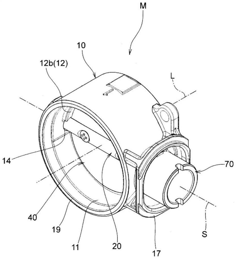
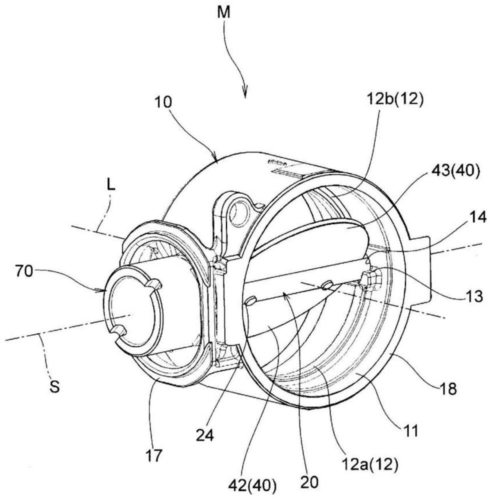
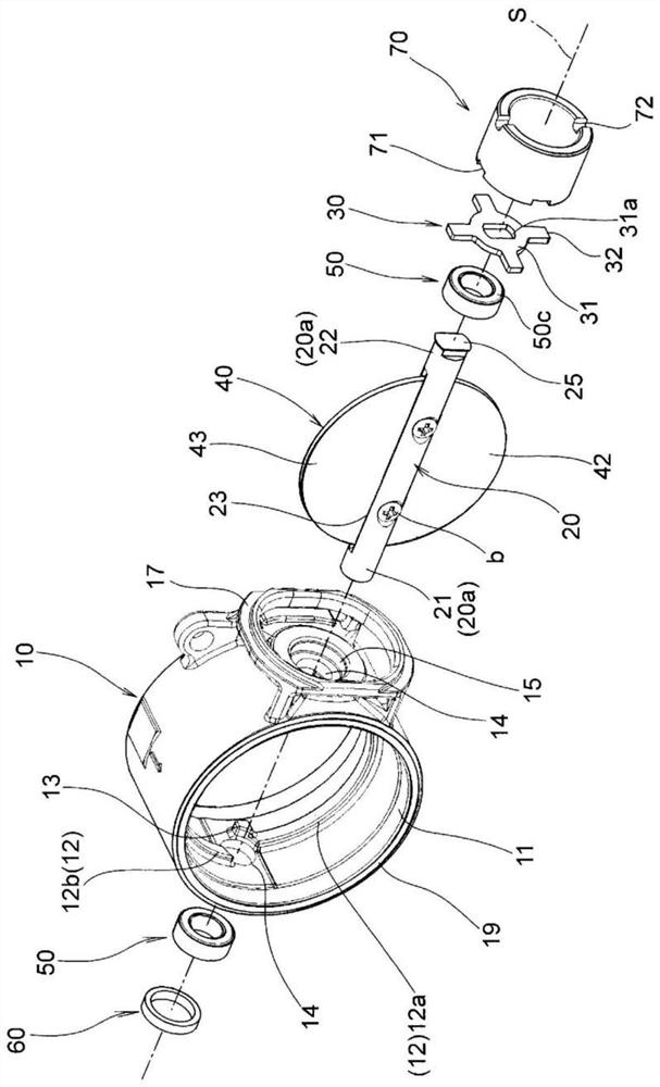
[0059] An embodiment of the valve device M such as Figure 1 to Figure 4 As shown, it includes a body 10 , a shaft 20 defining an axis S, a plate 30 , a valve core 40 , two bearing bushes 50 , a cover 60 , and a connecting member 70 .

[0060] The main body 10 is made of metal materials such as stainless steel and iron, and is cast by, for example, a dewaxing method. part 13, two shaft holes 14 through which the shaft 20 passes, two fitting holes 15 for fitting the bearing bush 50, fitting parts 16 for fitting the cover 60, the flange part 17, the first connecting part 18, The second connecting part 19 .

[0061] The passage 11 is formed in the form of a cylindrical passage having a circular cross-section with a certain inner diameter at the center on the center line L. As shown in FIG.

[0062] The seal portion 12 includes a first seal portion 12 a and a second seal...


PUM


Abstract

The present invention provides a valve device which suppresses noise or abrasion, ensures sliding performance, and can suppress cost increase, improve productivity, improve durability, improve functional reliability and the like. The valve device includes a body 10 that defines a passage through which a fluid flows, a shaft 20 that is movably supported with respect to the body and defines an axis S, a valve element 40 that is fixed to the shaft to open and close the passage; and a cylindrical bearing bush 50 that movably supports the shaft with respect to the body, includes a mixed region A0 in which a metal core material 51 and expanded graphite 52 are mixed with each other, and a first expanded graphite region A1 made of only the expanded graphite 52 such that the metal core material 51 is not exposed in an inner circumferential side region in contact with an outer circumferential surface 20a of the shaft.

Description

technical field [0001] The present invention relates to a valve device, which uses a bearing bush (also known as a sliding bearing) to support and fix the shaft of the spool of the switch passage, and particularly relates to a switch such as an engine exhaust system that circulates high-temperature exhaust gas. The valve device used in the passage. Background technique [0002] As a conventional valve device, the following valve device is known, including: a housing that defines a fluid passage; a valve that opens and closes the fluid passage; a valve shaft that drives the valve switch; and a sealing member that is embedded in the housing to rotate freely. The valve shaft is supported and sealed, and the sealing member has a shaft sealing structure. The core material (aggregate) is formed by weaving stainless steel wires into a net shape, and the carbon material is pressed and formed (for example, Patent Document 1 ). [0003] The sealing member is formed by compressing a ...

Claims


Application Information

Patent Timeline
Patent Type & Authority Applications(China)
IPC IPC(8): F16K1/226F16K1/32F16K1/36F16K27/02F02D9/10
CPCF16K1/2261F16K1/225F16K1/32F16K1/36F16K27/0218F02D9/10F02D9/1035F02D9/107F02D9/1075F16K1/224F02D9/106F16C17/02F16C17/10F16C33/121F16C33/124F16C33/14F16C2240/60F16C2361/91F16C2220/46F16C2226/30F16C2202/52F16C33/16F16J15/10F04B2201/0603F16J15/54F16J15/30
Inventor 石井利昌古山诚高山大辅
Owner MIKUNI CORP
Why Eureka
Try Eureka