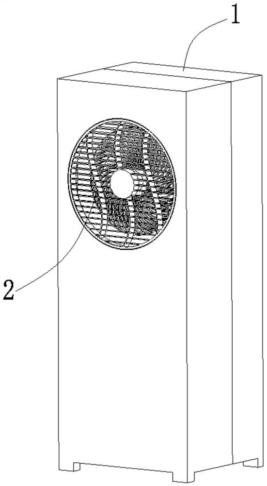
Novel axial-flow fan blade air conditioner fan
A technology of axial-flow blades and air-conditioning fans, which is applied in air-conditioning systems, airflow control components, space heating and ventilation, etc. It can solve the problems of no beneficial effect, short air supply distance, large product size, etc., and achieve easy Increased production and air supply distance, and the effect of a large cool area
- Summary
- Abstract
- Description
- Claims
- Application Information
AI Technical Summary
Problems solved by technology
Method used
Image

Examples
Embodiment 1
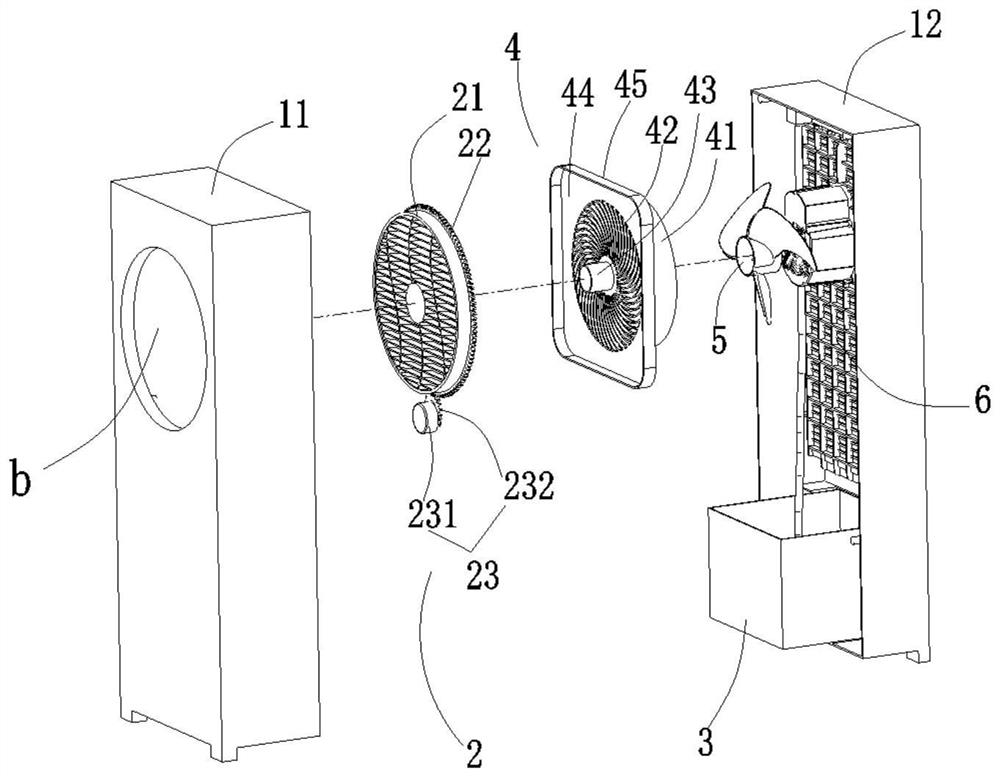
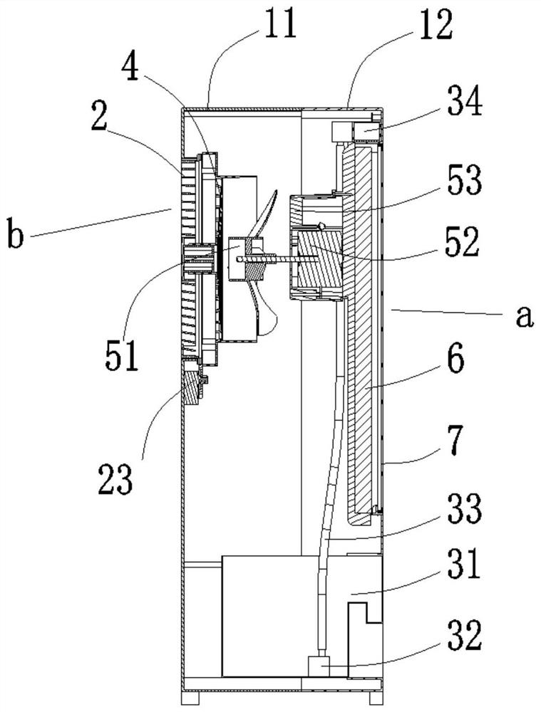
[0069] Such as figure 2 , image 3 , Figure 4 and Figure 5 shown.
[0070] The preferred air outlet b has a circular structure, and an air swing device 2 is also provided at the air outlet b. The driven gear 22 and the first driving device 23 on the surface, the air guide grid 24 for exhausting the wind is arranged on the swinging disc 21, and a hollow shaft connecting platform 43 is vertically arranged in the middle of the wind collecting grid 42 , the middle part of the wind swing disk 21 is provided with a shaft rod 25, the shaft rod 25 is rotatably arranged in the shaft rod connecting platform 43, and the wind collecting device 4 is fixed on the inner side of the front shell. Of course, the wind swing disc 21 and the wind collecting device 4 can also be connected in other ways, here only pointing out one of the preferred ways; the first drive device 23 is arranged on the inner side of the front shell 11, specifically including the first motor 231 and the first motor...
Embodiment 2
[0074] Such as Figure 6 , Figure 7 , Figure 8 and Figure 9 shown. The wind swing device 2 provided at the air outlet b is different from the wind swing device in Embodiment 1, the wind swing device 2 is arranged in the wind outlet cavity 45, and it includes a plurality of parallel and spaced blown wind blowers along the wind outlet cavity 45. The wind swing blade 2.1 and the second driving device 2.2, the two ends of the wind swing blade 2.1 are respectively provided with a rotating rod 2.3 coaxially arranged along its length direction, and one end of the wind swing blade 2.1 is also provided with a rotating rod 2.3 in the same direction as the rotating rod 2.3. The swing rod 2.4 arranged in parallel, the swing rod 2.4 and the rotating rod 2.3 are arranged at intervals; one opposite side surface of the air outlet cavity 45 is respectively provided with a plurality of pairs of shaft holes 45-1 coaxially arranged, one of the two sides A plurality of arc-shaped holes 45-2...
PUM
 Abstract
Description
Claims
Application Information
 - R&D
- Intellectual Property
- Life Sciences
- Materials
- Tech Scout
- Unparalleled Data Quality
- Higher Quality Content
- 60% Fewer Hallucinations
Browse by: Latest US Patents, China's latest patents, Technical Efficacy Thesaurus, Application Domain, Technology Topic, Popular Technical Reports.
© 2025 PatSnap. All rights reserved.Legal|Privacy policy|Modern Slavery Act Transparency Statement|Sitemap|About US| Contact US: help@patsnap.com