U/trasonic vortex flowmeter having clamp-on housing
A flowmeter and eddy current technology, applied in the improvement field of liquid flowmeter, can solve the problem of destroying the quality of the production process
- Summary
- Abstract
- Description
- Claims
- Application Information
AI Technical Summary
Problems solved by technology
Method used
Image

Examples
Embodiment Construction
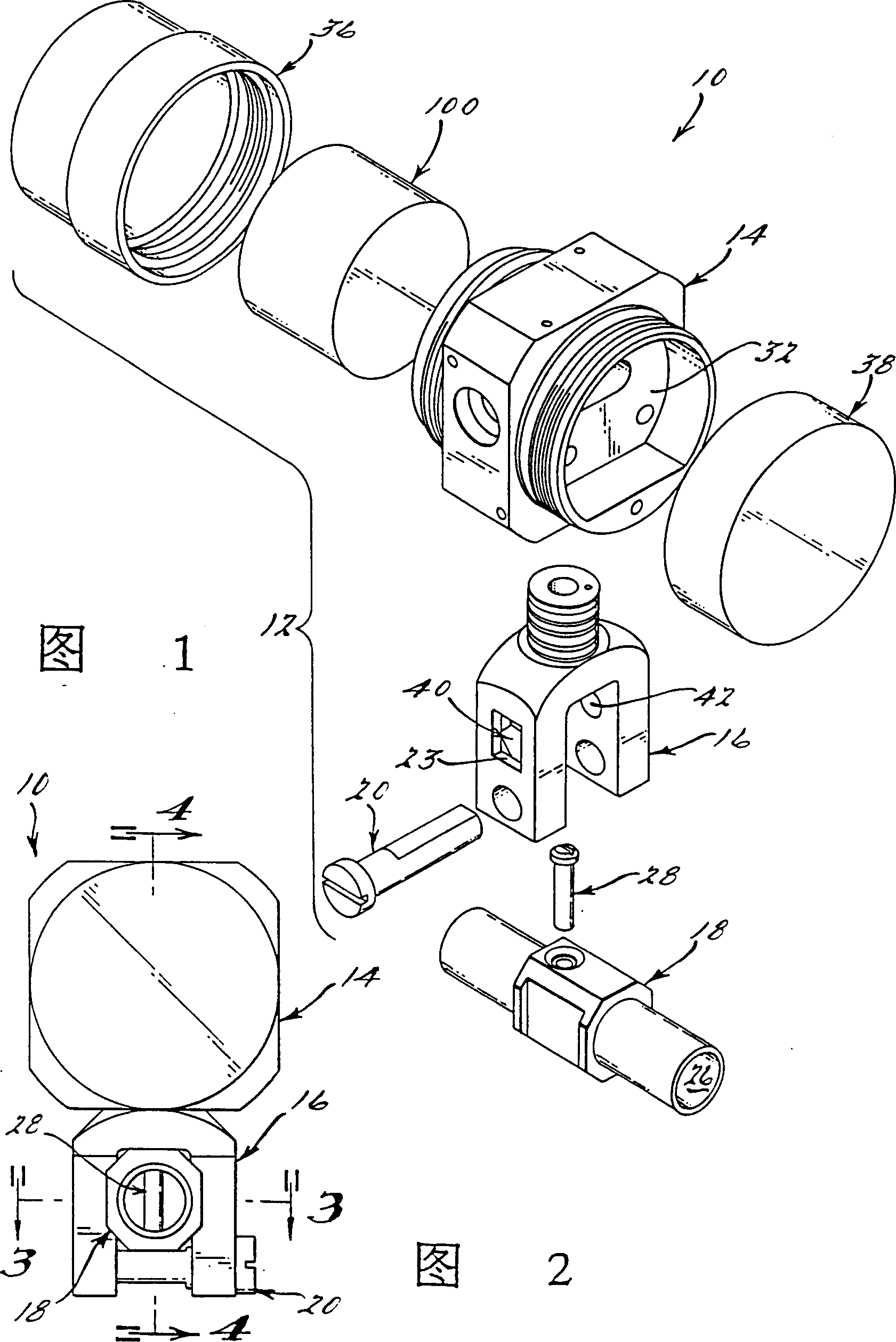
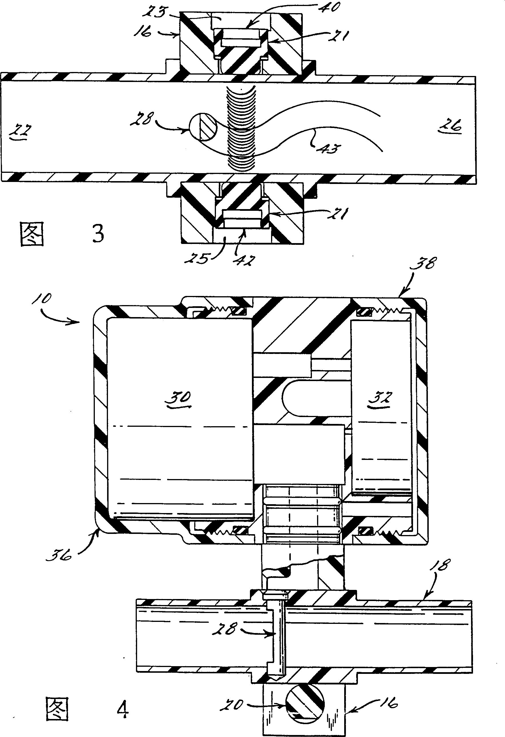
[0021] Referring to Figures 1-4, there is shown an ultrasonic vortex flowmeter 10 according to the present invention having a flowmeter housing 12 formed by a metering head 14 pivotally mounted on a slidingly mounted fork 16 . The fork 16 is arranged to slide over a separate bluff body-containing line connector 18 and is held in place by a locking profiled pin 20 . In addition, a pair of rubber bushes 21 are respectively placed in cavities 23 and 25 formed on opposite sides of the inner side of the fork 16 and made to protrude slightly outward from the inner surface of the fork so that once the fork As member 16 slides, a friction fit is formed between fork member 16 and the bluff body-containing tubing connector 18 .
[0022] During initial installation, the line connector 18 containing the bluff body is fitted to the liquid line or pipeline, after which the flow liquid to be detected enters a flow channel 24 containing the bluff body through the first open end 22 , and fina...
PUM
 Abstract
Description
Claims
Application Information