
Conveyor rack sheet metal part welding jig

A welding jig and sheet metal technology, applied in welding equipment, auxiliary welding equipment, welding/cutting auxiliary equipment, etc., can solve the problems of low assembly efficiency and poor accuracy, improve assembly efficiency and accuracy, and expand the scope of application , Improve the effect of assembly accuracy

Pending Publication Date: 2021-12-21
上海雷孚激光科技发展有限公司
View PDF1 Cites 2 Cited by
  • Summary
  • Abstract
  • Description
  • Claims
  • Application Information

AI Technical Summary

Problems solved by technology

[0006] In order to improve the problem of low assembly efficiency and poor precision of horizontal welding substrates and vertical welding substrates, this application provides a welding jig for sheet metal parts of conveyor racks

Method used


Image

  • Conveyor rack sheet metal part welding jig
  • Conveyor rack sheet metal part welding jig
  • Conveyor rack sheet metal part welding jig

Examples


Embodiment Construction

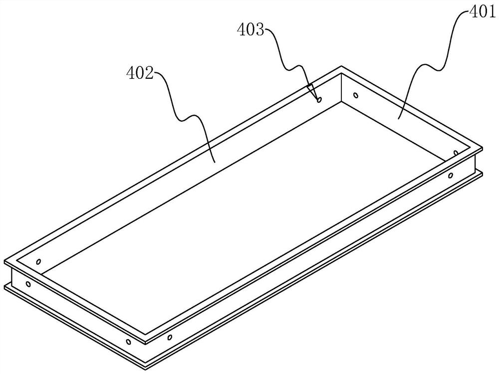
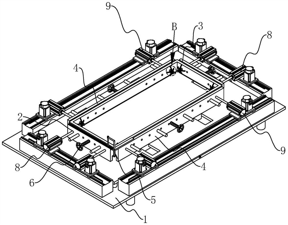
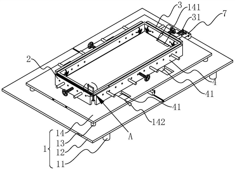
[0042] The following is attached Figure 2-9 The application is described in further detail.

[0043] The embodiment of the present application discloses a welding jig for sheet metal parts of a conveyor frame. refer to figure 2 and image 3 The conveyor frame sheet metal parts welding fixture includes a clamp body 1, including a plurality of first support legs 11, a first mounting plate 12 welded to the top ends of the plurality of first support legs 11, and welded to the first mounting plate 12. The second supporting legs 13 on the surface and the second mounting plate 14 welded to the tops of the multiple second supporting legs 13, the first mounting plate 12 and the second mounting plate 14 are both in the shape of a cuboid, and the length direction and the width direction are consistent.

[0044] refer to figure 2 and image 3 The positioning seat 2 and the first movable seat 3 are relatively arranged on the second mounting plate 14 , and the length direction of th...


PUM


Abstract

The invention discloses a conveyor rack sheet metal part welding jig. The conveyor rack sheet metal part welding jig comprises a clamp body, a positioning seat and a first movable seat are oppositely arranged on the clamp body, second movable seats are arranged on the portions, on the two sides of the positioning seat, of the clamp body, the clamp body is provided with an installation driving mechanism, and the installation driving mechanism comprises a driving assembly and a synchronous assembly. The positioning seat is used for being connected with any transverse welding base plate, the first movable seat is used for being connected with the other transverse welding base plate, and the two second movable seats are used for being connected with two longitudinal welding base plates correspondingly. The driving assembly is used for driving the first movable seat to get close to or get away from the positioning seat in the length direction of the clamp body, and when the driving assembly drives the first movable seat to move, the synchronous assembly drives the two second movable seats to get close to or get away from each other in the width direction of the clamp body. The conveyor rack sheet metal part welding jig has the effect of improving the assembly efficiency of the transverse welding base plates and the longitudinal welding base plates, the assembly precision can be better improved, and meanwhile the application range is wide.

Description

technical field [0001] The present application relates to the field of conveyor frame welding equipment, in particular to a welding jig for sheet metal parts of a conveyor frame. Background technique [0002] At present, in order to realize continuous automatic production, conveyors are used in many places, and the conveyor mainly includes a frame and a conveying drive structure installed on the frame. [0003] Usually each conveyor frame is composed of two horizontal welded base plates, two vertical welded base plates and several sheet metal parts. The horizontal welded base plate and the vertical welded base plate are welded end to end and assembled into a square frame, and then welded in the square frame. and assemble other sheet metal parts. Wherein, both the horizontal welding substrate and the vertical welding substrate are provided with mounting grooves. [0004] The Chinese patent with the application number CN201821752370.0 in the related technology proposes a con...

Claims


Application Information

Patent Timeline
Patent Type & Authority Applications(China)
IPC IPC(8): B23K37/04B23K37/00
CPCB23K37/04B23K37/0443B23K37/00
Inventor 黄超超
Owner 上海雷孚激光科技发展有限公司
Learn More