Large missile-borne radar radome erecting platform

A radar radome, a large-scale technology, applied to antennas, workbenches, radiation unit covers and other directions suitable for movable objects, can solve the problems of increased cost, heavy weight, and high protection requirements, and achieve equipment cost reduction and adaptability Strong, the effect of increasing the scope of application

Active Publication Date: 2021-12-21
CHINA ELECTRONIC TECH GRP CORP NO 38 RES INST
View PDF15 Cites 1 Cited by
  • Summary
  • Abstract
  • Description
  • Claims
  • Application Information

AI Technical Summary

Problems solved by technology

However, for large-scale missile-borne radome, there are many difficulties in the matching process of the hood, as follows: 1) The missile-borne radome is generally a conical irregular shape, which is heavy and not easy to clamp and fix; 2) There is a high-precision positioning pin guide between the radome and the cabin, and it is easy to be stuck due to the tilt and misalignment of the positioning pin during the assembly process; 3) The radome is made of non-metallic wave-transparent material, which is brittle and coated with special coating on the surface. 4) Different functions and different types of missile radome have different sizes and shapes, and the erection platform has poor compatibility with the model; 5) The matching and installation of the radome hood needs to be carried out in a dark room, and the platform operation severely limited space
The existing antenna erection devices are difficult to meet the high-precision and high-reliability erection requirements of large-scale missile radome in the dark room. In addition, the existing technology cannot adapt to different shapes of missile radome, resulting in the need to store and carry a large number of dedicated antenna erection devices , causing an increase in the cost of

Method used


Image

  • Large missile-borne radar radome erecting platform
  • Large missile-borne radar radome erecting platform
  • Large missile-borne radar radome erecting platform

Examples


Embodiment Construction

[0021] In order to make the purpose, technical solutions and advantages of the present invention clearer, the technical solutions of the present invention are clearly and completely described below in conjunction with specific embodiments and with reference to the accompanying drawings. Obviously, the described embodiments are part of the implementation of the present invention. example, not all examples. Based on the embodiments of the present invention, all other embodiments obtained by persons of ordinary skill in the art without creative efforts fall within the protection scope of the present invention.

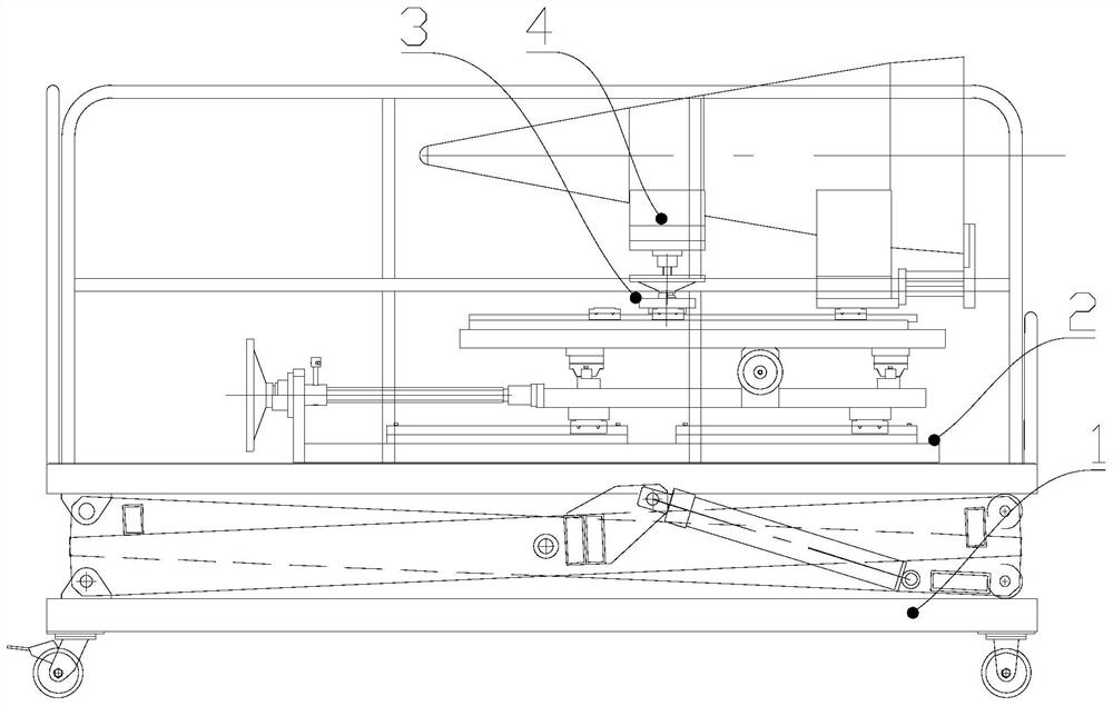
[0022] Such as figure 1 As shown, the present embodiment provides a large-scale missile-borne radome erecting platform, including a lifting mechanism 1, a coarse adjustment mechanism 2 cooperating with the lifting mechanism 1, a fine adjustment mechanism 3 cooperating with the coarse adjustment mechanism 2, and a fine adjustment mechanism 3. The installation mechanism 4 ...


PUM


Abstract

The invention provides a large missile-borne radar radome erecting platform. The platform comprises a lifting mechanism, a coarse adjustment mechanism matched with the lifting mechanism, a fine adjustment mechanism matched with the coarse adjustment mechanism and a mounting mechanism matched with the fine adjustment mechanism; a radome can be fixed to the mounting mechanism; the lifting mechanism can drive the coarse adjustment mechanism to change the height, the coarse adjustment mechanism can drive the fine adjustment mechanism to adjust the position in the horizontal plane, and the fine adjustment mechanism can drive the mounting mechanism to change the height. Rapid coarse adjustment of the position of the radome is achieved through the lifting mechanism and the coarse adjustment mechanism, the radome is moved to the designated position, then accurate adjustment of the position is conducted through the fine adjustment mechanism, the high-precision requirement for head cover matching can be met, the matched mounting mechanism can be replaced according to the type of the radome, the adaptability is high, and the equipment cost is obviously reduced.

Description

technical field [0001] The invention relates to the technical field of radar manufacturing, in particular to a platform for erecting a large missile-borne radar radome. Background technique [0002] In order to measure and correct the influence of the radome on the performance of the radar antenna, it is an important task in the development process of the seeker to carry out the performance parameter matching of the warhead radome and the radar seeker based on the far-field anechoic chamber (hereinafter referred to as "hood matching"). However, for large-scale missile-borne radome, there are many difficulties in the matching process of the hood, as follows: 1) The missile-borne radome is generally a conical irregular shape, which is heavy and not easy to clamp and fix; 2) There is a high-precision positioning pin guide between the radome and the cabin, and it is easy to be stuck due to the tilt and misalignment of the positioning pin during the assembly process; 3) The radom...

Claims


Application Information

Patent Timeline
Patent Type & Authority Applications(China)
IPC IPC(8): B25B27/00B25B11/02B25H1/08B25H1/16H01Q1/28H01Q1/42
CPCB25B27/00H01Q1/42H01Q1/28B25H1/08B25H1/16B25B11/02
Inventor 赵凯洪肇斌范梦龙刘琳汪旭宏汪君祝先周织建
Owner CHINA ELECTRONIC TECH GRP CORP NO 38 RES INST
Why Eureka
Try Eureka