Sampling holding circuit applied to high-speed high-precision circuit

A sample-hold circuit, high-precision technology, applied in electrical components, electrical signal transmission systems, signal transmission systems, etc., can solve the problems of reducing the SNDR of the sample-hold circuit, being easily affected by the second harmonic, and the DC gain of the amplifier is small, etc. Achieve the effect of reducing on-resistance, high DC gain, and reducing transient spikes

Active Publication Date: 2013-05-08
TIANJIN UNIV
View PDF4 Cites 23 Cited by
  • Summary
  • Abstract
  • Description
  • Claims
  • Application Information

AI Technical Summary

Problems solved by technology

[0009] (1) Since the circuit adopts a single-ended structure, its output swing is small, the influence of the common mode signal is large, and it is easily affected by the second harmonic
[0010] (2) In traditional sample and hold circuits, there is no low-pass filter circuit connected between the input voltage signal and the sampling switch, and the input voltage signal is easily affected by the back-end drive circuit, resulting in transient peaks
[0011] (3) The sampling switch often uses a MOS switch or a CMOS switch, which has a large on-resistance and changes with the amplitude of the input voltage signal
The change of on-resistance determines that the output voltage of the sample-and-hold circuit is established at different speeds, and voltages with different establishment accuracy are generated on the sampling capacitor, and there will be even-order harmonic interference in the output voltage, which reduces the SNDR of the sample-and-hold circuit (no stray dynamics scope)
[0012] (4) Traditional sample-and-hold circuits often use ordinary folded cascode operational amplifiers, which have small DC gain and limited accuracy

Method used


Image

  • Sampling holding circuit applied to high-speed high-precision circuit
  • Sampling holding circuit applied to high-speed high-precision circuit
  • Sampling holding circuit applied to high-speed high-precision circuit

Examples


Embodiment Construction

[0028] The present invention will be further described in detail below in combination with specific embodiments.

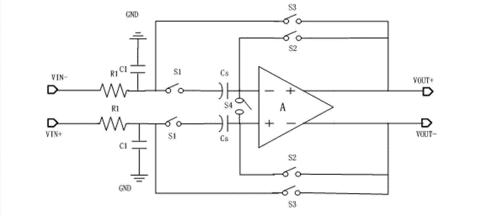
[0029] Such as figure 2 As shown, the present invention is a sample-and-hold circuit applied to high-speed and high-precision circuits, which is characterized in that it includes a fully differential operational amplifier, two sampling capacitors Cs, two sampling switches S1 and two S2 of five selection switches, Two S3, one S4 and two low-pass filter circuits formed by resistor R1 and capacitor C1; the fully differential operational amplifier is a gain-enhanced folded cascode fully differential operational amplifier; the sampling and holding circuit of the present invention is fully The structure of connecting the positive and negative input ends of the differential operational amplifier is exactly the same. Taking the connection structure of one input end of the fully differential operational amplifier as an example, the signal input end is connected to the sam...


PUM


Abstract

The invention discloses a sampling holding circuit applied to a high-speed high-precision circuit. The sampling holding circuit comprises a full-differential type operational amplifier, two sampling capacitors Cs, two sampling switches S1 and five selective switches and a low-pass filter circuit formed by a resistor R1 and a capacitor C1. The full-differential type operational amplifier is a gain enhancement folding cascade full-differential type operational amplifier, a sampling switch S1 is a grid voltage bootstrap switch, connected structures of the positive end and the negative end of the full-differential type operational amplifier are completely same, and a signal input end passes through the low-pass filter circuit to be connected with a lower pole plate of the sampling capacitors Cs through the sampling switches S1. A selective switch S3 is connected with the lower pole plate of the sampling capacitors Cs and the output end of the full-differential type operational amplifier. An upper pole plate of the sampling capacitors Cs is connected with the input end of the full-differential type operational amplifier, a selective switch S4 is connected with upper pole plates of the two sampling capacitors Cs, and a selective switch S2 is connected with the input end and the output end of the full-differential type operational amplifier. The sampling holding circuit can achieve sampling holding of the input signals in the high-speed high-precision circuit.

Description

technical field [0001] The invention relates to the field of data acquisition, in particular to an analog signal and digital signal conversion device. Background technique [0002] Sample and hold circuits are widely used in the field of analog signal processing, especially in analog signal and digital signal conversion circuits, which require the front-end input voltage signal to be collected and held for a period of time for subsequent circuits to process the signal. Quick response, high enough sampling and holding accuracy to meet the requirements of the entire circuit system, and long enough holding time, good linearity. [0003] Traditional sample-and-hold circuits, such as figure 1 As shown, it is usually composed of an operational amplifier, a sampling capacitor, a sampling switch, and two selection switches. Its work is divided into two stages and controlled by a two-phase clock. Wherein, in the first stage, the switch S1 and the switch S2 are turned on, the switch...

Claims


Application Information

Patent Timeline
Patent Type & Authority Applications(China)
IPC IPC(8): H03M1/54
Inventor 赵毅强岳森张杨庞瑞龙夏璠
Owner TIANJIN UNIV
Why Eureka
Try Eureka