Inflatable water-jet propeller

A water jet propulsion, inflatable technology, applied in the direction of ship propulsion, propulsion components, ship components, etc., to achieve the effects of suppressing collapse strength, improving acoustic stealth performance, and improving cavitation performance

Pending Publication Date: 2021-12-21
708TH RES INST OF CSSC
View PDF5 Cites 0 Cited by
  • Summary
  • Abstract
  • Description
  • Claims
  • Application Information

AI Technical Summary

Problems solved by technology

[0005] The technical problem to be solved in the present invention is: how to reduce the problem of cavitation noise in the water jet propeller

Method used


Image

  • Inflatable water-jet propeller
  • Inflatable water-jet propeller
  • Inflatable water-jet propeller

Examples


Embodiment 1

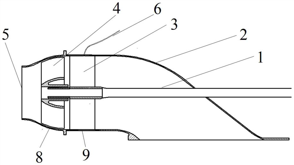
[0028] The invention provides an inflatable water jet propeller, such as figure 1 As shown, it includes shaft 1, inlet channel 2, guide vane 3, impeller 4, nozzle 5, air supply pipe 6, pump casing, one end of the pump casing is provided with nozzle 5, and the pump casing is provided with impeller 4 and inlet flow 2, the impeller 4 is set between the nozzle 5 and the inlet flow channel 2, and the impeller 4 is fixed on the shaft 1 that can drive the impeller 4 to rotate. Between Road 2. The pump casing includes an inlet channel 2, a guide vane housing 9 and an impeller housing 8. One end of the inlet channel 2 is connected to one end of the impeller housing 8 through the guide vane housing 9, and the other end of the impeller housing 8 is provided with a nozzle. 5. The guide vane housing 9 is provided with a guide vane 3, the guide vane 3 is fixed on the shaft sleeve, and the shaft sleeve is sleeved on the shaft 1, so that the shaft 1 can rotate in the shaft sleeve. Guide van...

Embodiment 2

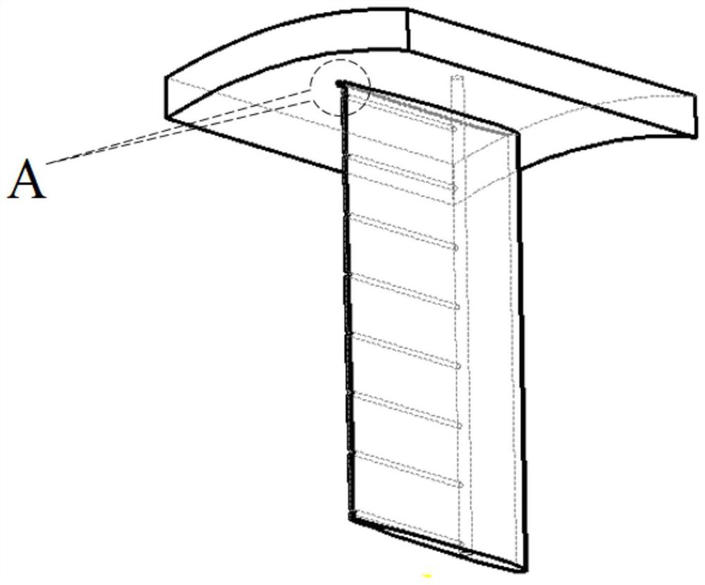
[0036] In this example, if Figure 5 As shown, the internal air supply pipeline 3.1 includes a plurality of individual pipelines, one end of each individual pipeline is respectively connected to the air supply pipeline 6, and the other end of each individual pipeline is respectively connected to an air injection port 3.2. Each pipeline can be controlled independently.

[0037] Others are the same as in Example 1.

Embodiment 3

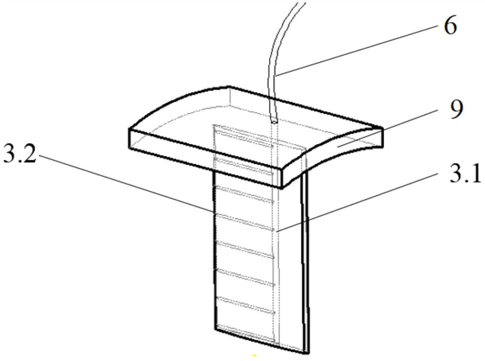
[0039] In this example, if Image 6 As shown, the air charging hole is arranged at the entrance of the inlet flow channel 2, that is, the inflatable device is set at the entrance of the inlet flow channel 2, the connection position of the air supply pipeline 6 and the pump casing is located at the entrance of the inlet flow channel 2, and the air supply pipeline 6 One end passes through the pump casing at the inlet position of the inlet channel 2 and is connected with the inflation device. For some water jet propellers, the cavitation primary position is near the entrance of the inlet flow channel 2, that is, the inner wall of the inlet flow channel 2 near the position of the air supply pipeline 6 in the figure. At this time, the gas supply pipeline 6 can be arranged at the inlet of the inlet flow channel 2, and the generation of cavitation can be suppressed by means of inflation.

[0040] Others are the same as in Example 1.


PUM


Abstract

The invention discloses an inflatable water-jet propeller which comprises a pump shell, a nozzle is arranged at one end of the pump shell, an impeller and an inlet runner are arranged in the pump shell, the impeller is arranged between the nozzle and the inlet runner, the impeller is fixed on a shaft capable of driving the impeller to rotate. The inflatable water-jet propeller is characterized in that an inflating device is arranged in the inlet runner; and the inflation device is connected with an air storage device through an air supply pipeline. According to the inflatable water-jet propeller, the cavitation performance of the water-jet propeller is improved, and the cavitation noise of the water-jet propeller is reduced.

Description

technical field [0001] The invention relates to a water jet propeller, in particular to an inflatable water jet propeller, which belongs to the technical field of ship propulsion. Background technique [0002] The water jet propeller includes an inlet flow channel, a water jet propulsion pump (impeller, impeller housing, guide vane body (composed of guide vanes and guide vane housing)) and a nozzle, wherein the inlet flow channel, impeller housing, guide vane housing The body and the nozzle constitute the piping system of the water jet propeller. The impeller and guide vane are located in the pipeline system. The impeller rotates at high speed to convert the power of the main engine into fluid energy, and the high-speed water is sprayed out from the nozzle. The momentum difference between the inflow fluid in the inlet channel and the fluid ejected from the nozzle is the thrust source of the waterjet propeller, which pushes the ship or other carrier forward in the water, and...

Claims


Application Information

Patent Timeline
Patent Type & Authority Applications(China)
IPC IPC(8): B63H11/08B63H11/09
CPCB63H11/08B63H11/09
Inventor 李宁万初瑞林辉戴原星严鹏张岩刘正浩
Owner 708TH RES INST OF CSSC
Why Eureka
Try Eureka