
Yarn guiding equipment with carding function for textile cotton yarn feeding

A cotton yarn and textile technology, applied in the field of wire equipment, can solve the problems of incomplete surface treatment of textile cotton yarn, and achieve the effect of ensuring comprehensiveness and stability and facilitating processing

Inactive Publication Date: 2021-12-21
安徽旭之杰纺织科技有限公司
View PDF0 Cites 1 Cited by
  • Summary
  • Abstract
  • Description
  • Claims
  • Application Information

AI Technical Summary

Problems solved by technology

[0006] The invention provides a wire device with carding function for textile cotton yarn feeding, which solves the problem of incomplete surface treatment of textile cotton yarn during carding

Method used


Image

  • Yarn guiding equipment with carding function for textile cotton yarn feeding
  • Yarn guiding equipment with carding function for textile cotton yarn feeding
  • Yarn guiding equipment with carding function for textile cotton yarn feeding

Examples


Embodiment 1

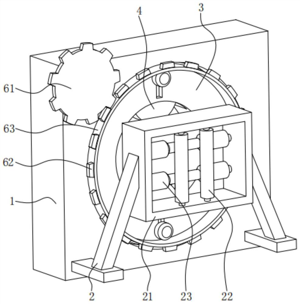
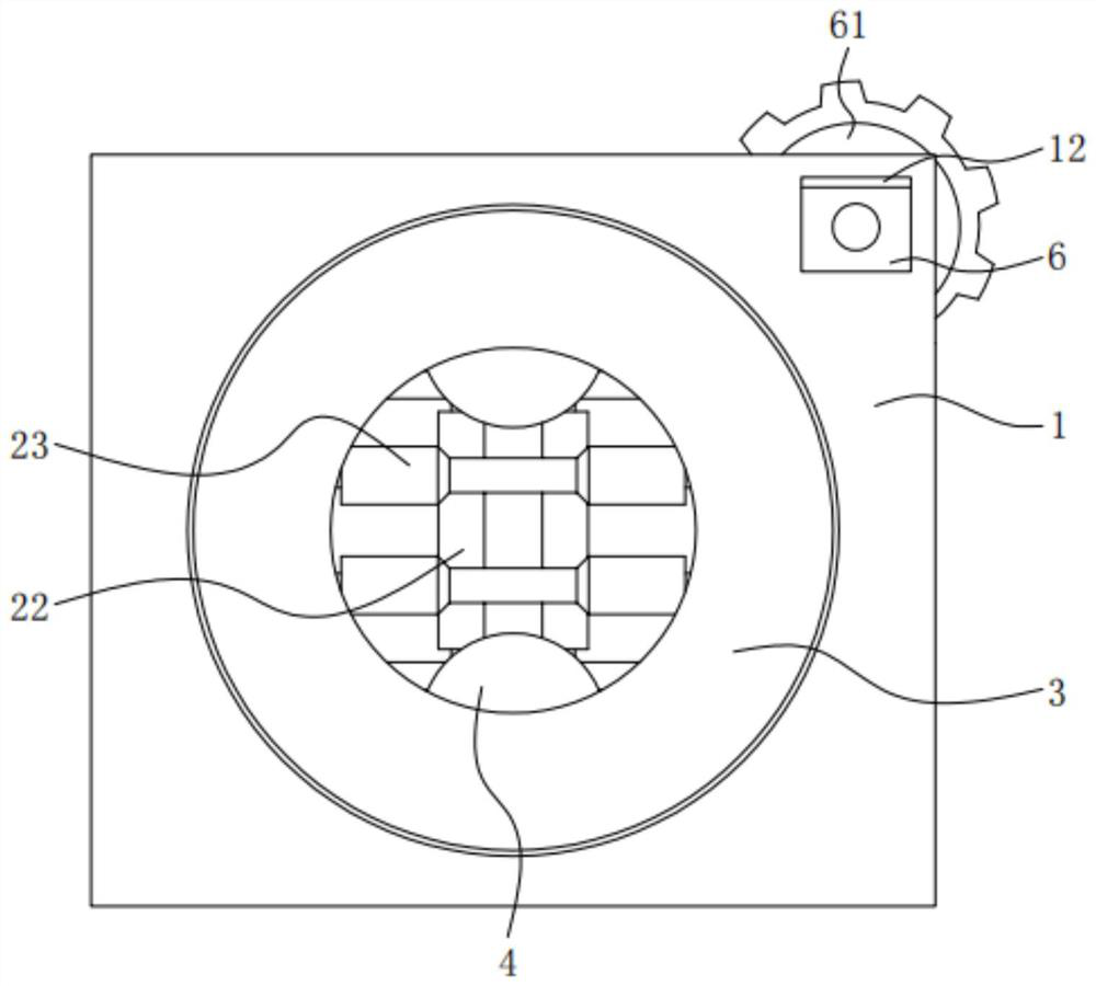
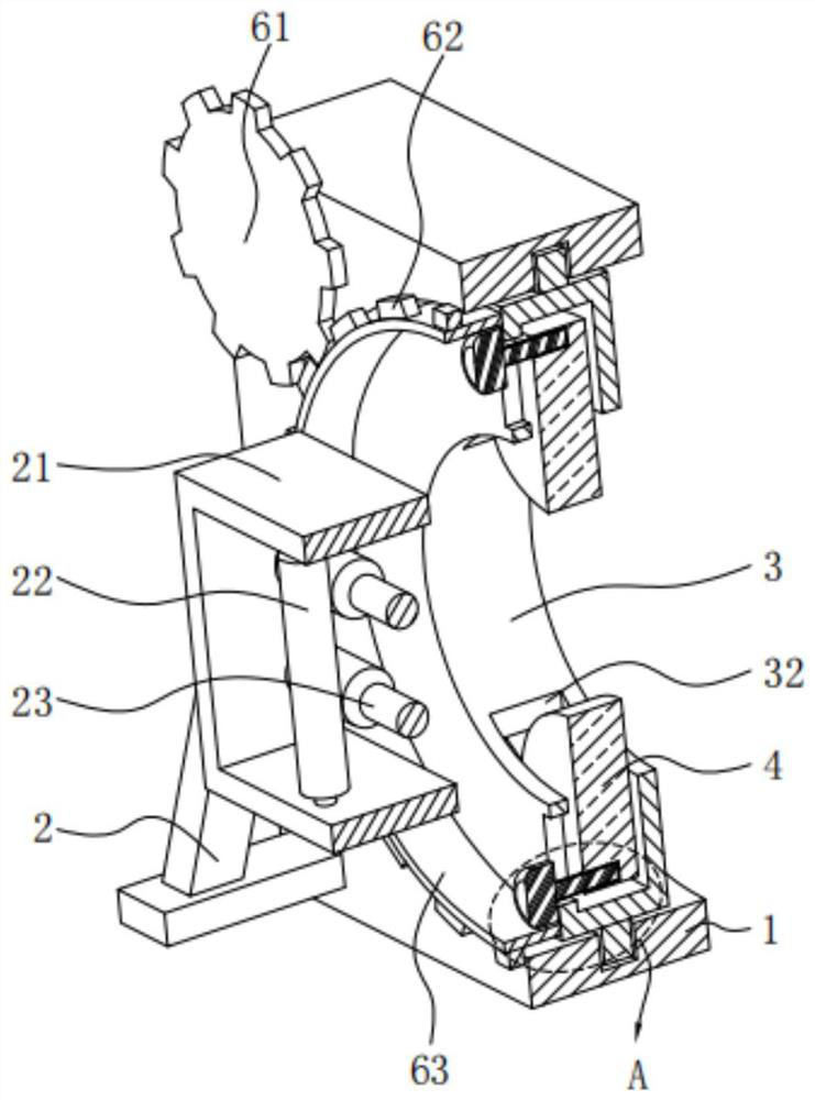
[0038] A kind of wire equipment with carding function for textile cotton yarn feeding comprises: a mounting frame 1, which is provided with a rotating groove 11 and a mounting groove 12; a connecting frame 2, one side of which is fixedly installed on the On the surface of the mounting frame 1, the inner side of the connecting frame 2 is fixedly connected with a fixed frame 21, and the inner side of the fixed frame 21 is respectively provided with a first conveying roller 22 and a second conveying roller 23; the rotating disk 3, the The surface of the rotating disk 3 is movably installed in the inside of the rotating groove 11 by connecting the outer ring 31; the carding disk 4, the carding disk 4 is installed on the surface of the rotating disk 3; the adjusting motor 6, the adjusting motor 6 One side is fixedly connected to the inner surface of the installation groove 12, the output end of the adjustment motor 6 is fixedly connected with a driving gear 61, and the surface of th...

Embodiment 2

[0056] The inner side of the rotating disk 3 is provided with a telescopic groove 32 and a connecting hole 33, and the surface of the carding disk 4 is movably installed in the inside of the telescopic groove 32, and the carding disk 4 is provided with an adjustment groove 41, and the adjustment The inner surface of the groove 41 is threadedly connected with the adjusting screw shaft 5 .

[0057] The fixedly installed carding disc 4 is movably installed on the rotary disc 3, so that the carding disc 4 can be conveniently adjusted on the rotary disc 3 by adjusting the screw shaft 5, so as to facilitate the adjustment of the contact degree between the carding disc 4 and the textile cotton yarn, Thereby, it is convenient to fully comb the surface of the textile cotton yarn, and at the same time, the adjustable carding disc 4 can adjust the number of operations according to the needs of use, so as to meet the different needs of users.

[0058] The interior of the connecting hole 3...


PUM


Abstract

The invention provides yarn guiding equipment with a carding function for textile cotton yarn feeding. The yarn guiding equipment with the carding function for spinning cotton yarn feeding comprises a mounting frame provided with a rotating groove and a mounting groove, and a connecting frame with one side fixedly mounted on the surface of the mounting frame. According to the yarn guiding equipment with the carding function for textile cotton yarn feeding, a first conveying roller and a second conveying roller which are crisscrossed are arranged at the input end of the mounting frame, so that input textile cotton yarn can be conveniently limited and conveyed in advance, and the stability of conveying the cotton yarn to the inner side of the mounting frame is guaranteed; and when the textile cotton yarn is input into the mounting frame, an adjusting motor drives a rotating disc on the inner side to rotate through a gear connecting structure, and the rotating disc drives a carding disc on the inner side to card and maintain the surface of the textile cotton yarn, so that the carding comprehensiveness and stability during yarn guiding of the textile cotton yarn are guaranteed, and processing of the textile cotton yarn is facilitated.

Description

technical field [0001] The invention relates to the technical field of textile processing, in particular to a wire device with carding function for textile cotton yarn feeding. Background technique [0002] With the continuous development of textile technology, cotton yarn is the yarn processed from cotton fiber through spinning process. It is called cotton thread after plying. The yarn is made of high-quality raw materials. The fibers in the yarn are straight and parallel, with less knots, good luster, evenness and high strength. This type of cotton yarn is mostly used for weaving high-end fabrics. [0003] In the process of textile cotton yarn preparation, when the cotton yarn is fed, the surface of the yarn is intricate, and it is necessary to perform surface treatment before the yarn is merged to ensure the stability of the yarn surface and avoid carrying a large amount of fiber wool on the yarn surface. lint or dust, which affects the quality of yarn production. [00...

Claims


Application Information

Patent Timeline
IPC IPC(8): D01H13/04D02J3/00
CPCD01H13/04D02J3/00
Inventor 鲍春晖白韧
Owner 安徽旭之杰纺织科技有限公司
Learn More