Eureka AIR delivers breakthrough ideas for toughest innovation challenges, trusted by R&D personnel around the world.

Urban drainage pipeline sludge separation system

A separation system, urban drainage technology, applied in the sewer system, waterway system, water/sludge/sewage treatment, etc., can solve the problems of scaling, affecting normal sewage discharge, and increasing pollution load.

Active Publication Date: 2021-12-21
ANHUI UNIVERSITY OF TECHNOLOGY AND SCIENCE
View PDF4 Cites 2 Cited by
  • Summary
  • Abstract
  • Description
  • Claims
  • Application Information

AI Technical Summary

Problems solved by technology

[0003]The blockage of drainage pipes is a very common problem in daily life. There are generally several types of drainage pipe dredging: 1. Foreign objects accidentally fall into the newly installed pipes Or blockage caused by installation errors, generally use a pipe dredger to directly dredge or replace the pipeline; 2. Some pipelines will scale after a period of use, making the inner diameter of the pipeline thinner and affecting normal water discharge. This kind of dredging must use high pressure Clean the pipes with water, remove the dirt on the inner wall of the pipes to expand the inner diameter of the sewer pipes, and dredge the drainage pipes.
[0004]But in real life, in addition to the above two situations that will lead to blockage of drainage pipes, rainwater, especially heavy precipitation in extreme weather, and surface runoff will cause increased pollution loads, and the bottom of drainage pipes will There will be continuous accumulation of sediment and some fine garbage at the end, long-term accumulation will cause the inner diameter of the drainage pipe to become thinner, which will affect the normal drainage

Method used


Image

  • Urban drainage pipeline sludge separation system
  • Urban drainage pipeline sludge separation system
  • Urban drainage pipeline sludge separation system

Examples


Embodiment Construction

[0025] The following will clearly and completely describe the technical solutions in the embodiments of the present invention with reference to the accompanying drawings in the embodiments of the present invention. Obviously, the described embodiments are only some, not all, embodiments of the present invention. Based on the embodiments of the present invention, all other embodiments obtained by persons of ordinary skill in the art without making creative efforts belong to the protection scope of the present invention.

[0026]In the description of the present invention, it should be noted that the terms "center", "upper", "lower", "left", "right", "vertical", "horizontal", "inner", "outer" etc. The indicated orientation or positional relationship is based on the orientation or positional relationship shown in the drawings, and is only for the convenience of describing the present invention and simplifying the description, rather than indicating or implying that the referred de...


PUM


Abstract

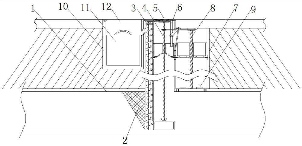
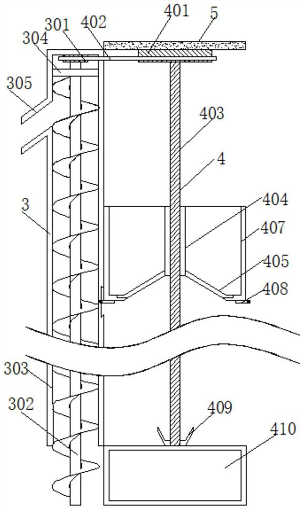
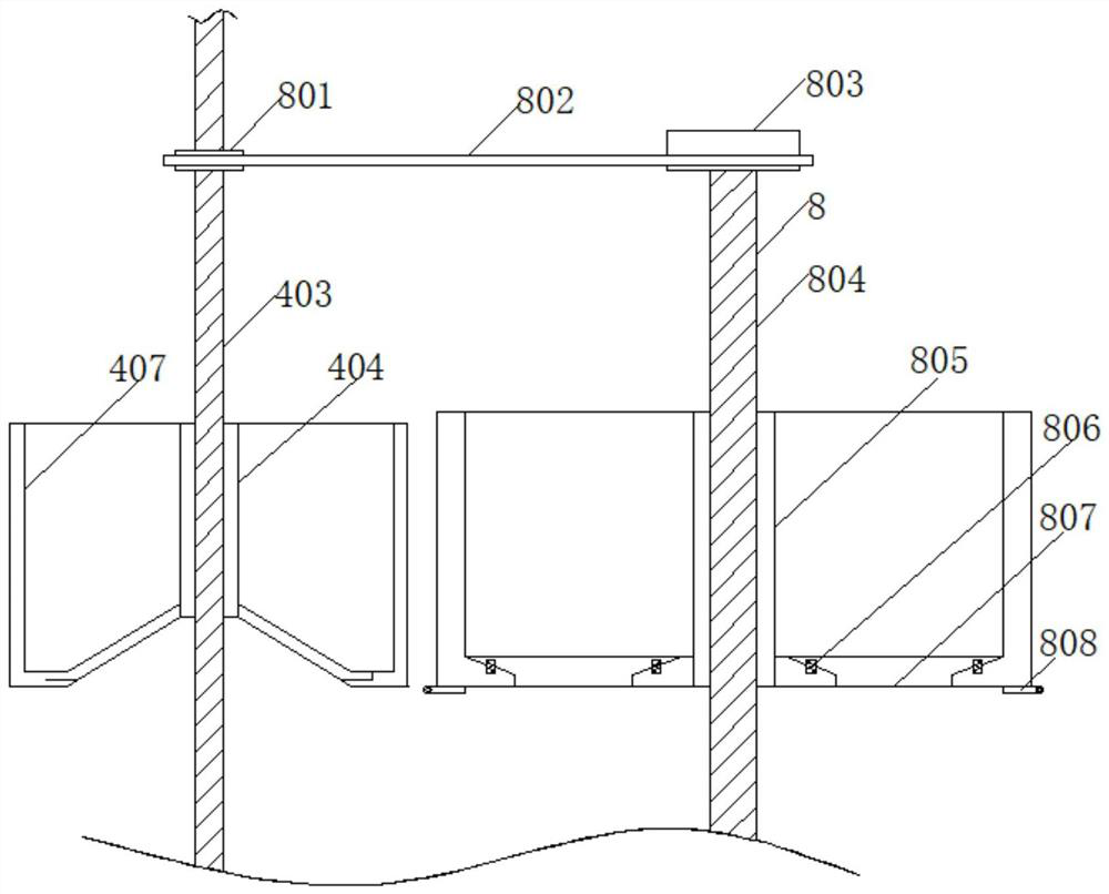
The invention discloses an urban drainage pipeline sludge separation system, and relates to the field of urban sewage. The urban drainage pipeline sludge separation system comprises a drainage pipeline, two groups of filter screens are fixed on the inner wall of the drainage pipeline, a sludge discharging mechanism is fixed between the two groups of filter screens, a collection mechanism is fixed on one side of the sludge discharging mechanism, and the top end of the collection mechanism is connected with a drainage pipeline well lid. A swing mechanism is arranged at the bottom end, located on one side of the collecting mechanism, of the drainage pipeline well lid. According to the urban drainage pipeline sludge separation system, by arranging the drainage pipeline, a filter screen, the sludge discharging mechanism, the collection mechanism, a drainage pipeline well lid, a sludge collection box and the swing mechanism, a first chain moves to drive a first gear disc to rotate at a high speed, the first gear disc rotates to drive an auger to rotate at the high speed, and silt and garbage in the drainage pipeline are sucked into a sludge suction pipe by the auger through centrifugal force; the silt moves in the sludge suction pipe along with rotation of the auger, and when the silt moves to the position of a sludge discharging pipe, the silt moves into the sludge collection box through a sludge discharging opening.

Description

technical field [0001] The invention relates to the field of urban sewage, in particular to an urban drainage pipe sludge separation system. Background technique [0002] Drainage pipe is a kind of urban public facility, which appeared as early as in ancient Rome. The prototype of modern drainage pipe originated in Paris, France. Up to now, Paris still has the largest urban drainage pipe system in the world. Generally speaking, the drainage pipe system It is used to collect and discharge domestic wastewater generated in cities and industrial wastewater generated in industrial production. [0003] Drain pipe blockage is a very common problem in daily life. Drainage pipe dredging is generally divided into several types: 1. When a new pipe is installed, a foreign object is accidentally dropped or the blockage is caused by an installation error. Generally, a pipe dredger is used to directly dredge it. Or replace the pipe; 2. Some pipes will scale after a period of use, making t...

Claims


Application Information

Patent Timeline
Patent Type & Authority Applications(China)
IPC IPC(8): E03F3/04E03F5/14E03F7/00B01D29/50B01D29/03B01D35/02B01D29/94
CPCE03F3/04E03F5/14E03F7/00B01D29/50B01D29/03B01D35/02B01D29/94
Inventor 韦学玉杨晓凡李济源宋伟迪张玉凤
Owner ANHUI UNIVERSITY OF TECHNOLOGY AND SCIENCE
Why Eureka
Eureka Blog
Learn More